A high-speed drive motor shaft for new energy vehicles and its manufacturing process

A new energy vehicle, motor shaft technology, applied in shafts, couplings, mechanical equipment and other directions, can solve the problems of inconvenient assembly and disassembly of motor shafts, poor heat dissipation effect, etc. Strong pressure effect

Active Publication Date: 2021-06-11
HUBEI JIANFENG TECH INC
View PDF0 Cites 0 Cited by
  • Summary
  • Abstract
  • Description
  • Claims
  • Application Information

AI Technical Summary

Problems solved by technology

[0003] The purpose of the present invention is to solve the shortcomings of the existing motor shaft in the prior art that it is not easy to assemble and disassemble, and the heat dissipation effect is poor, and propose a high-speed drive motor shaft for new energy vehicles and its manufacturing process

Method used


Image

  • A high-speed drive motor shaft for new energy vehicles and its manufacturing process
  • A high-speed drive motor shaft for new energy vehicles and its manufacturing process
  • A high-speed drive motor shaft for new energy vehicles and its manufacturing process

Examples


Embodiment 1

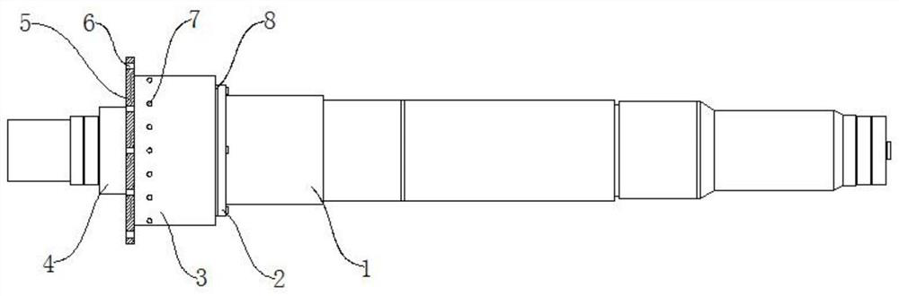
[0030] refer to Figure 1-4 , a high-speed drive motor shaft for new energy vehicles, including a first main shaft 1 and a second main shaft 4, the first main shaft 1 and the second main shaft 4 are fixedly connected, and one end on the outer wall of the first main shaft 1 is fixedly connected to a limited position Ring 2, the limit ring 2 close to the second main shaft 4 is fixedly connected with a shaft sleeve 8 by several screws, and the shaft sleeve 8 is set on the second main shaft 4. Through this design, the motor shaft can be quickly and conveniently The shaft sleeve is fixedly assembled on the motor shaft, and the motor shaft sleeve can be easily disassembled, which greatly facilitates the assembly process between the motor shaft main shaft and the shaft sleeve, and the assembly structure is stable and reliable. The stability during the rotating operation of the motor shaft can be improved.

[0031] Two key grooves 10 are provided on the inner wall of the bushing 8 cl...

Embodiment 2

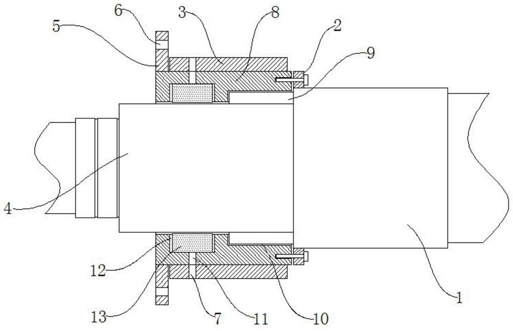
[0033] refer to figure 2 and Figure 4 , as another preferred embodiment of the present invention, the difference from Embodiment 1 is that the heat dissipation mechanism includes a groove 12, the groove 12 is set on the inner wall of the shaft sleeve 8, and a plurality of heat dissipation The fins 13 and the inner bottom of the groove 12 are evenly provided with several second heat dissipation channels 11, and the several second heat dissipation channels 11 are respectively connected to the several first heat dissipation channels 7, and the groove 12 is a groove of an annular structure , and a plurality of cooling fins 13 are annularly fixedly connected inside the groove 12, and several second heat dissipation channels 11 are circumferentially opened at the bottom of the groove 12. Through this design, it is possible to effectively The effect of cooling the motor shaft is achieved. The heat generated during the rotation and operation of the motor shaft will quickly and sequ...

Embodiment 3

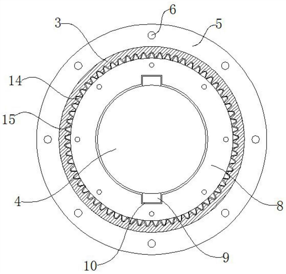
[0035] refer to image 3, as another preferred embodiment of the present invention, the difference from Embodiment 1 is that the clamping mechanism includes an annular clamping strip 14 and an annular clamping groove 15, the annular clamping strip 14 is fixedly connected on the outer side wall of the shaft sleeve 8, and the annular clamping The groove 15 is set on the inner side wall of the protective cover 3, and the annular clamping strip 14 and the annular clamping groove 15 are compatible with each other. The annular clamping strip 14 is a ring-shaped sawtooth-shaped structural member, and the annular clamping groove 15 is an annular sawtooth-shaped groove. , and the ring clip 14 and the ring clip groove 15 are engaged with each other. Through this design, the protective sleeve 3 and the shaft sleeve 8 can be connected together more firmly, and the protective sleeve 3 can be better Play a protective role to the shaft sleeve 8.

[0036] The present invention also provides ...


PUM


Abstract

The invention relates to the technical field of new energy automobile accessories, in particular to a high-speed drive motor shaft for new energy automobiles, including a first main shaft and a second main shaft, the first main shaft and the second main shaft are fixedly connected, and the outer wall of the first main shaft The upper end is fixedly connected with the limit ring, and the limit ring is fixedly connected with a shaft sleeve by several screws on the side close to the second main shaft, and the shaft sleeve is set on the second main shaft, and the inner wall of the shaft sleeve is provided with two two key grooves, and the two key grooves are symmetrically arranged, two connecting keys are fixedly connected to the side of the second main shaft close to the first main shaft, and a heat dissipation mechanism is also arranged on the inner wall of the shaft sleeve, and the outer wall of the shaft sleeve is far away from the first main shaft. One side is fixedly connected with a mounting plate, and a plurality of mounting holes are evenly opened in a ring shape on the mounting plate, and a protective sleeve is provided on the outer side of the shaft sleeve. The high-speed drive motor shaft of the new energy vehicle has a good heat dissipation capability, is easy to disassemble and assemble, and operates stably.

Description

technical field [0001] The invention relates to the technical field of new energy automobile accessories, in particular to a motor shaft driven by a new energy automobile at high speed and a manufacturing process thereof. Background technique [0002] New energy vehicles are a new direction for the development of the contemporary automotive industry. In the process of production and processing of new energy vehicles, the motor shaft is an extremely important transmission component in one of the auto parts. The motor shaft is mainly composed of a main shaft and a shaft sleeve, while the main shaft and the shaft sleeve of the motor shaft in the prior art are mostly of an integrated structure, or the shaft sleeve is pressed onto the main shaft by a press-fitting device. The assembly process of the main shaft and the shaft sleeve of the motor shaft is very cumbersome and complicated, and it will be more troublesome to disassemble, and in the process of the motor shaft rotating a...

Claims


Application Information

Patent Timeline
Patent Type & Authority Patents(China)
IPC IPC(8): F16C3/02F16D1/033H02K7/00H02K9/00B23P15/14
CPCB23P15/14F16C3/023F16D1/033H02K7/003H02K9/00
Inventor 谢赤彪
Owner HUBEI JIANFENG TECH INC
Why Eureka
Try Eureka