
A photovoltaic thermoelectric power generation device with good cooling effect

A technology of temperature difference power generation and cooling effect, which is applied in solar thermal power generation, generators/motors, electrical components, etc., can solve the problems of lower heating efficiency, lower power generation efficiency, smaller temperature difference between hot end plate and cold end plate, etc., to improve Effects of power generation efficiency, improved usability, and ease of heating

Active Publication Date: 2021-02-19
MUDANJIANG NORMAL UNIV
View PDF9 Cites 0 Cited by
  • Summary
  • Abstract
  • Description
  • Claims
  • Application Information

AI Technical Summary

Problems solved by technology

[0003] However, during the use of the existing photovoltaic thermoelectric power generation device, due to the continuous operation of the equipment, the temperature of the cold end plate gradually increases, resulting in the gradual reduction of the temperature difference between the hot end plate and the cold end plate, thereby reducing the power generation efficiency, not only that , after long-term use of the existing photovoltaic thermoelectric power generation device, the surface of the hot end plate is easy to accumulate dust, which affects the absorption of sunlight, resulting in a decrease in heating efficiency, which reduces the temperature difference between the hot end plate and the cold end plate, and the power generation capacity of the power generation device reduce, thereby reducing the practicability of existing photovoltaic thermoelectric power generation devices

Method used


Image

  • A photovoltaic thermoelectric power generation device with good cooling effect
  • A photovoltaic thermoelectric power generation device with good cooling effect
  • A photovoltaic thermoelectric power generation device with good cooling effect

Examples


Embodiment Construction

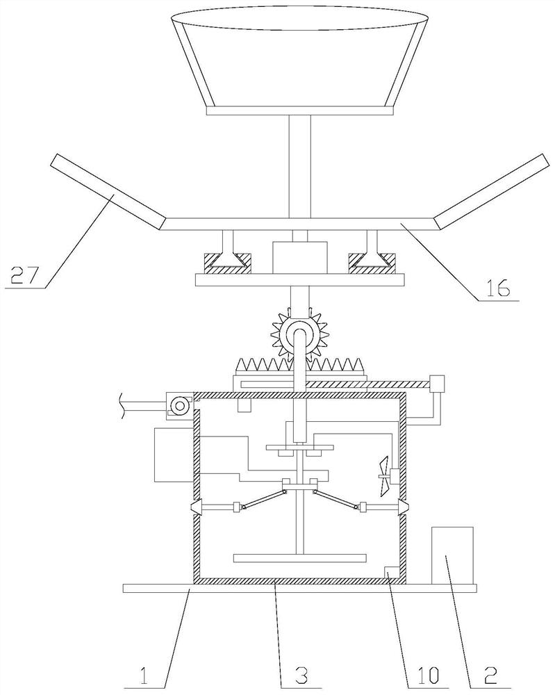
[0024] The present invention is described in further detail now in conjunction with accompanying drawing. These drawings are all simplified schematic diagrams, which only illustrate the basic structure of the present invention in a schematic manner, so they only show the configurations related to the present invention.

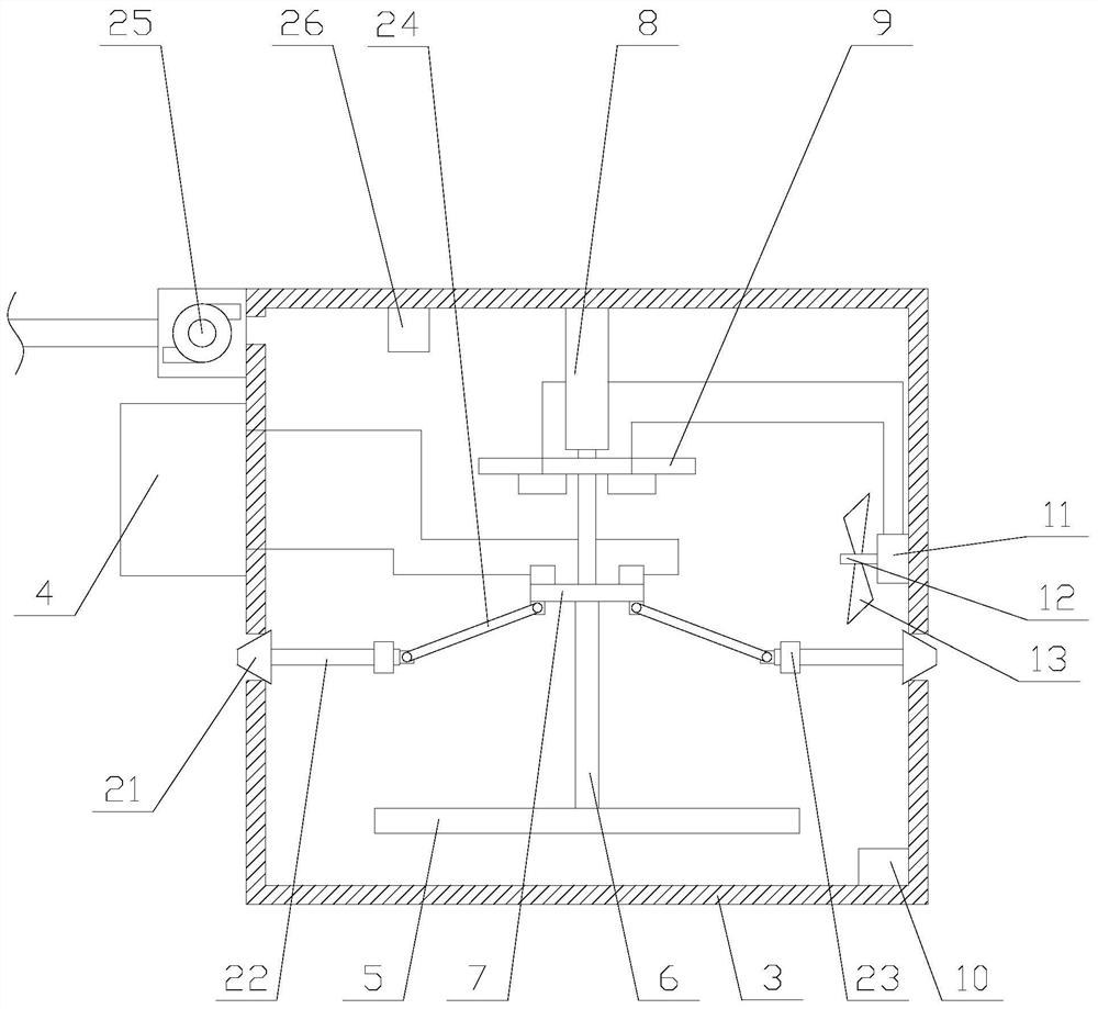
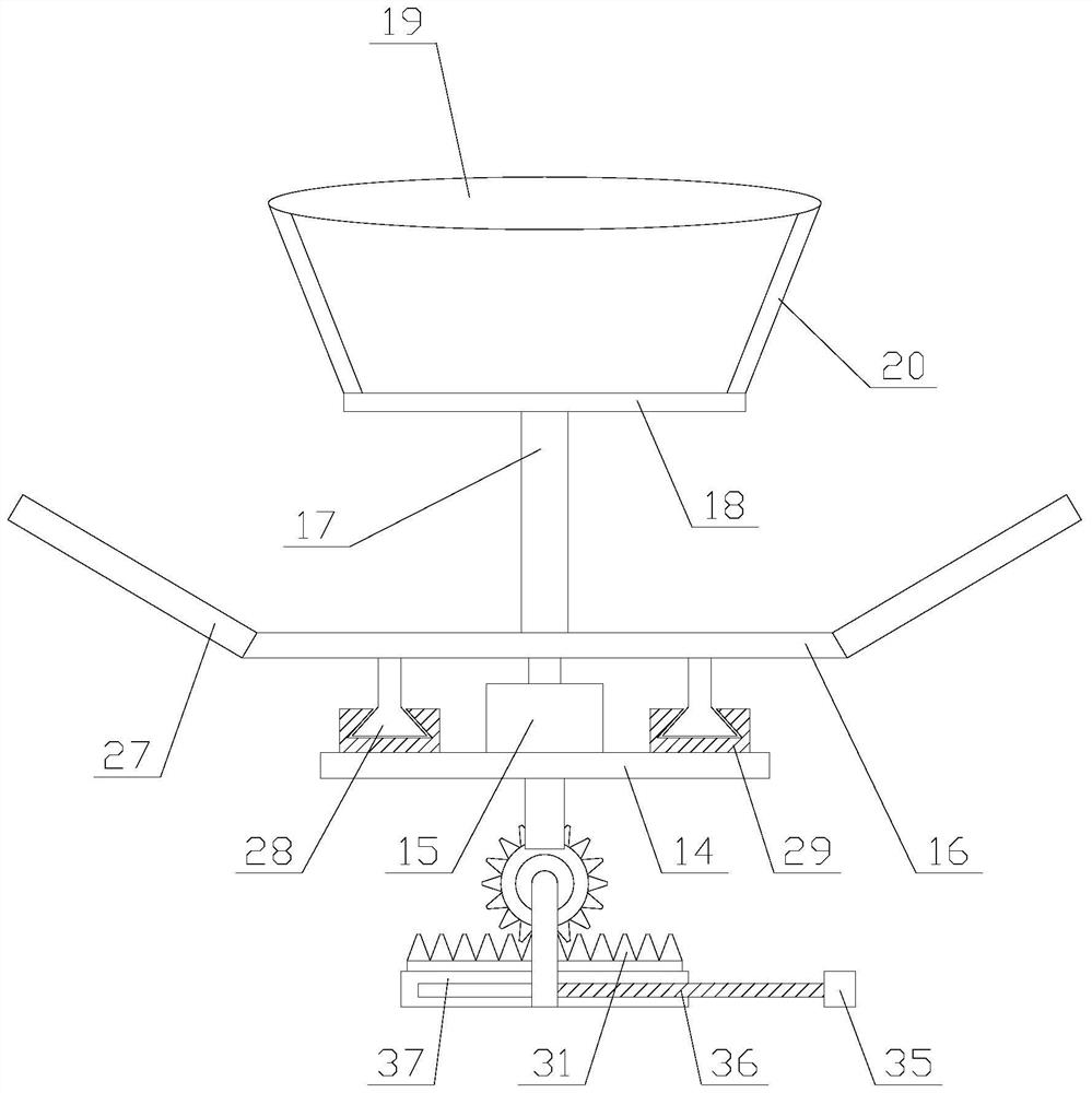
[0025] Such as figure 1 As shown, a photovoltaic thermoelectric power generation device with good cooling effect includes a base 1, a processor 2, a cooling mechanism and a heating mechanism, the processor 2 is fixed above the base 1, and the processor 2 is provided with a PLC. The heating mechanism and the cooling mechanism are sequentially arranged above the base 1 from top to bottom;

[0026] PLC, that is, programmable logic controller, which uses a type of programmable memory for its internal storage program, executes user-oriented instructions such as logical operations, sequence control, timing, counting and arithmetic operations, and passes digital or ...


PUM


Abstract

The invention relates to a photovoltaic thermoelectric power generation device with a good cooling effect. The device comprises a base, a processor, a cooling mechanism and a heating mechanism, and the cooling mechanism comprises a water tank, a storage battery, a cold end plate arranged in the water tank, a connecting rod and a cooling assembly. The heating mechanism comprises an adjusting assembly, an adjusting plate, a first motor, a rotary disc, a supporting rod, a hot end plate, a convex lens and a plurality of inclined rods. According to the photovoltaic temperature difference power generation device with the good cooling effect, an aqueous solution absorbs heat of the cold end plate through the cooling mechanism; a good cooling effect on the cold end plate is achieved through ventilation and heat dissipation; the sunlight radiation quantity absorbed by the hot end plate is increased through the convex lens and a reflector in the heating mechanism, and the rotary disc is driven to rotate through the first motor, so that dust impurities are thrown out by centrifugal force, the cleanness of the hot end plate and the convex lens is ensured, quick heating is facilitated, the temperature difference is increased, the power generation efficiency is improved, and the practicability of the equipment is further improved.

Description

technical field [0001] The invention relates to the field of photovoltaic thermoelectric power generation, in particular to a photovoltaic thermoelectric power generation device with good cooling effect. Background technique [0002] Solar energy is a renewable energy source that can provide thermal radiation energy to heat up the irradiated objects. The thermoelectric power generation module includes a hot end plate, a cold end plate and a thermoelectric power generation element. Using sunlight to irradiate the hot end plate of the thermoelectric power generation module will cause the hot end plate to heat up rapidly, and there will be a large temperature difference between the cold end plate and the hot end plate. The thermoelectric power generation module will generate electricity and connect to the battery for charging. Based on this principle , People have invented various types of photovoltaic thermoelectric power generation devices, and put them into the power system...

Claims


Application Information

Patent Timeline
Patent Type & Authority Patents(China)
IPC IPC(8): F24S23/30F24S23/70F24S80/00H02N11/00F24S50/00
CPCF24S23/30F24S23/70F24S50/00F24S80/00H02N11/002Y02E10/40
Inventor 白龙付东辉王淑玉
Owner MUDANJIANG NORMAL UNIV
Learn More