Cooling equipment for engineering

A cooling equipment and engineering technology, applied in household refrigeration equipment, lighting and heating equipment, applications, etc., can solve problems such as reducing the quality of the wall, wall cracking, etc., to avoid excessive temperature difference, improve water replenishment and reduce moisture, accelerate The effect of velocity of circulation

Active Publication Date: 2020-04-14
中冷制冷设备股份有限公司
View PDF6 Cites 2 Cited by
  • Summary
  • Abstract
  • Description
  • Claims
  • Application Information

AI Technical Summary

Problems solved by technology

[0002] Today's construction projects are all built with concrete and steel bars. Concrete is mixed with cement and other materials, which will expand and contract under the sun's exposure, especially when the building is just built, there is too much water in the wall , Extracting too much water at once will cause the wall to crack and reduce the quality of the wall. Therefore, it is necessary to spray cold water on the wall in the early stage of building construction to increase the moisture in the wall and reduce the temperature of the wall.

Method used


Image

  • Cooling equipment for engineering
  • Cooling equipment for engineering
  • Cooling equipment for engineering

Examples


Embodiment

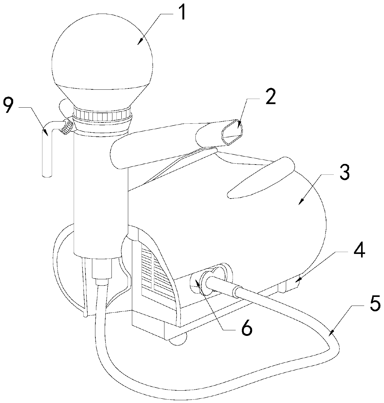
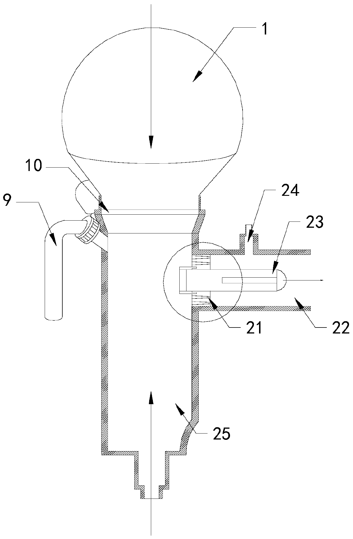
[0027] see Figure 1-Figure 7 , the present invention provides a cooling device for engineering, its structure includes a hot water tank 1, an atomizer 2, a pump body 3, a base 4, a water pipe 5, a nozzle 6, and a valve 9, and the bottom of the pump body 3 is provided with a base 4. The base 4 and the pump body 3 are fixedly connected, and the side of the pump body 3 is provided with a connecting port 6, and a water pipe 5 is connected to the connecting port 6, and an atomizer 2 is installed at the end of the water pipe 5 A hot water tank 1 is installed on the top of the atomizer 2 far away from the water pipe 5 , and a valve 9 is installed at the connection position between the hot water tank 1 and the atomizer 2 .

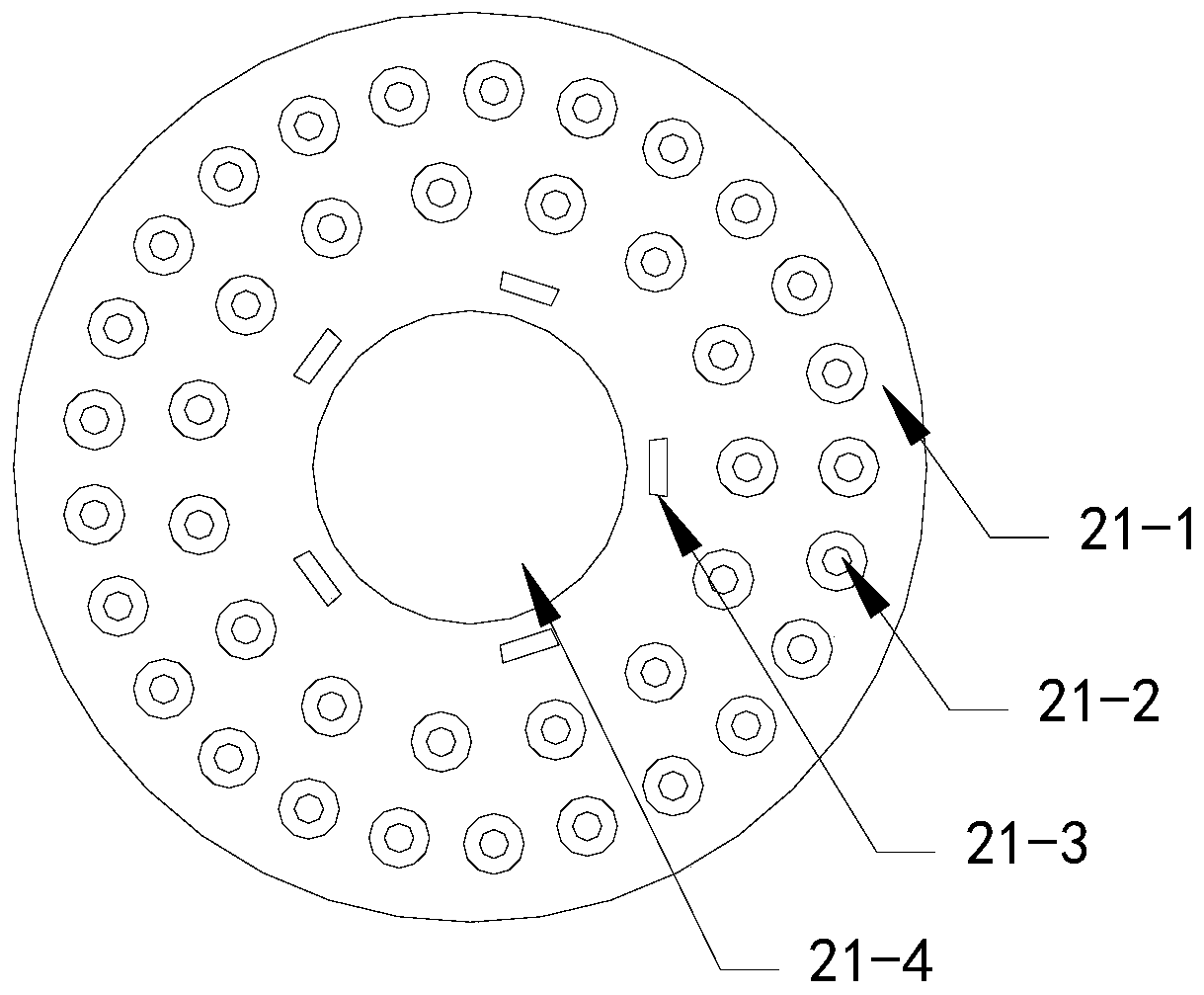
[0028] The atomizer 2 is provided with a grid plate 21, a mist outlet pipe 22, a shunt column 23, an air hole 24, and a liquid circulation pipe 25. The liquid circulation pipe 25 is a hollow pipe body that penetrates up and down, and the liquid circulation pipe 2...


PUM


Abstract

The invention discloses cooling equipment for engineering. The cooling equipment structurally comprises a hot water tank, an atomizer, a pump body, a base, a water pipe, a pipe connecting opening anda valve, wherein the base is arranged at the bottom of the pump body, the base is fixedly connected with the pump body, the pipe connecting opening is formed in the side face of the pump body, the water pipe is connected to the pipe connecting opening, the atomizer is installed at the tail end of the water pipe, the top end, away from the water pipe, of the atomizer, is provided with the hot watertank, and the connecting position between the hot water tank and the atomizer is provided with the valve. According to the cooling equipment for engineering, after the pump body pumps cold water andthe cold water is atomized by the atomizer, the water is integrally atomized, the volume of each drop of water is reduced throughout the day, and the surface contact area is increased, so that the water drops are in full contact with concrete, water supply for a wall body can be improved, and the temperature of the wall body is reduced; and in addition, hot water from the hot water tank and the cold water pumped by the pump body intersect up and down to neutralize the temperature, and meanwhile the amount of the fed hot water is adjusted through a water dividing plate, and therefore the cooling equipment is suitable for wall body wetting in different environments, and the situation that the wall body cracks or gaps are generated due to the fact that the temperature difference is too largecan be avoided.

Description

technical field [0001] The invention relates to the field of cooling equipment, in particular to engineering cooling equipment. Background technique [0002] Today's construction projects are all built with concrete and steel bars. Concrete is mixed with cement and other materials, which will expand and contract under the sun's exposure, especially when the building is just built, there is too much water in the wall , Extracting too much water at once will cause the wall to crack and reduce the quality of the wall. Therefore, it is necessary to spray cold water on the wall in the early stage of building construction to increase the moisture in the wall and reduce the temperature of the wall. Contents of the invention [0003] Aiming at the deficiencies of the prior art, the present invention is realized through the following technical solutions: a kind of cooling equipment for engineering, its structure includes a hot water tank, an atomizer, a pump body, a base, a water p...

Claims


Application Information

Patent Timeline
Patent Type & Authority Applications(China)
IPC IPC(8): F25D1/02B05B7/04E04B2/00
CPCB05B7/04E04B2/00F25D1/02
Inventor 林计生
Owner 中冷制冷设备股份有限公司
Why Eureka
Try Eureka