Pressure vessel

a pressure vessel and pressure technology, applied in water installations, flushing devices, constructions, etc., can solve the problems of wasting water, requiring a considerable force to press down the pressing device, and the disadvantages of conventional pressure vessels, so as to reduce manufacturing costs, improve production efficiency, and reduce waste of water.

Inactive Publication Date: 2007-09-06
GLOBE UNION INDAL
View PDF9 Cites 11 Cited by
  • Summary
  • Abstract
  • Description
  • Claims
  • Application Information

AI Technical Summary

Benefits of technology

[0009] The main characteristics of the invention are a main vessel, an air entry valve, a water entry valve, a drain valve and a control valve. The drain valve is provided with a valve base set on the top of the main vessel, a piston unit inserted inside the valve base able to be moved upwards and a spring installed between the piston unit and the valve base. In addition, the pressured water in the main vessel coming from the water entry valve and the air entry valve can be stored in the control valve and guided to a chamber formed between the piston unit and the valve base, via controlling the control valve, enabling the piston unit to surpass the elastic force and the water pressure so as to move up to separate from a drain exit of the main vessel for flushing a toilet.
[0010] The present invention, based on guiding water to force the piston member to move upwards for separating from the drain exit, has a simpler structure than that of a conventional one based on releasing pressure, able to achieve a quick assembly and a lower cost of manufacturing. Moreover, even if the tube guiding the pressured water is damaged or leaking, the drain exit is not to be opened by accident for flushing, able to prevent water waste. Therefore, the present invention has effects of saving water, quick refilling water and good clean up.

Problems solved by technology

Commonly, a conventional vessel used for a toilet to carry out flushing is based on gravity force and water level drop, which, actually, are not strong enough to flush down, always needing more water to clean up the toilet, causing a waste of water.
The conventional pressure vessel has still disadvantages as described below.
In practice, it needs a considerable force to press down the pressing device initially because a strong rebounding force possessed by a compressed spring in the drain valve must be surpassed, inconvenient for operation.
Next, another pressure auxiliary double flushing system disclosed in a U.S. Pat. No. 2004 / 0194200 can, though, solve the disadvantages mentioned above, it has a very complicated structure, difficult for assembly and having a high cost.
Relatively, it has a higher possibility of breakdown.

Method used


Image

  • Pressure vessel
  • Pressure vessel
  • Pressure vessel

Examples


Embodiment Construction

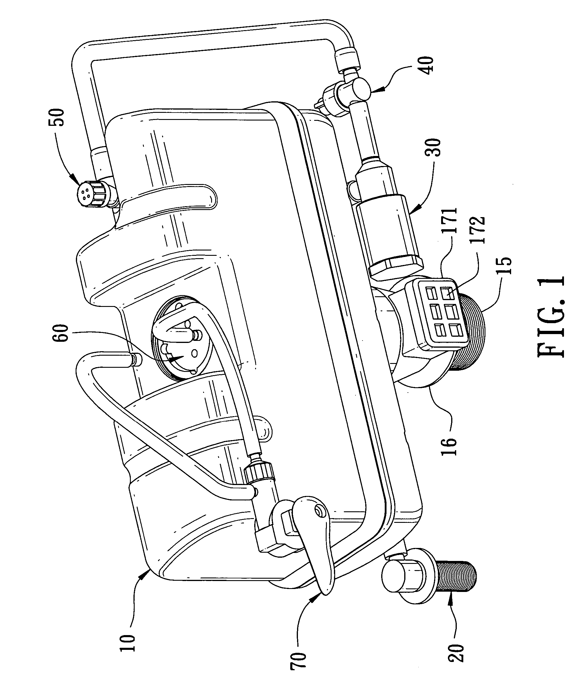
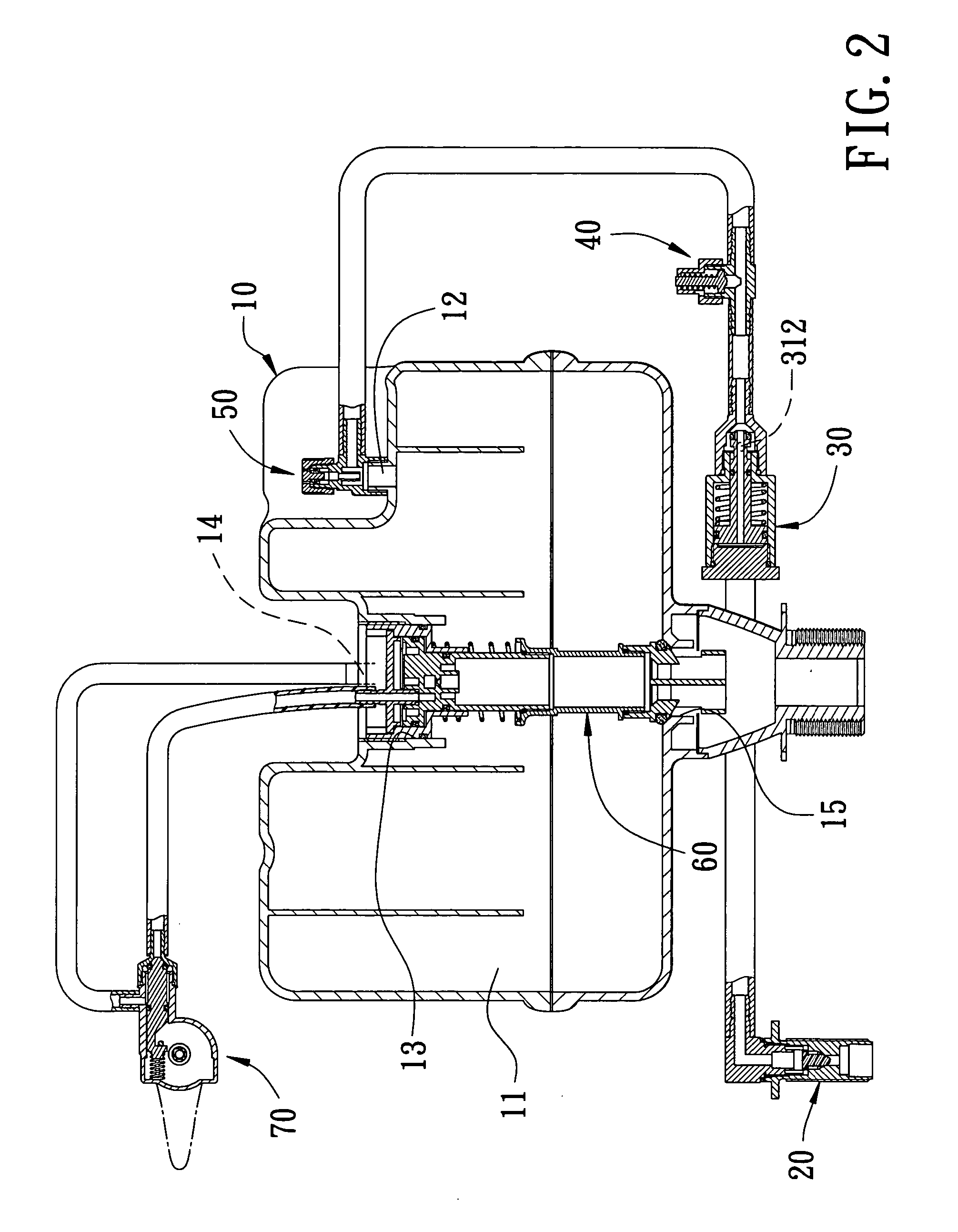
[0032] As shown in FIGS. 1 an 2, a preferred embodiment of a pressure vessel for a toilet in the present invention includes a main vessel 10 installed inside a toilet vessel (not shown in Figures), a water entry valve 20 fixed under the left of the vessel and connected with an inlet tube, a pressure stabilizing valve 30 set behind the water entry valve 20, a pressure releasing valve 40 set behind the pressure stabilizing valve 30, an air entry valve 50 set behind the air entry valve 40 and connected with the main vessel 10 and located at the right upper side of the main vessel 10, a drain valve 60 fixed at the interior center of the main vessel 10 and a control valve 70 fixed at the upper left side of the vessel 10 and connected with the main vessel 10 and the drain valve 60 extending and fixed in the center portion of the main vessel 10.

[0033] As shown in FIGS. 2 and 3, the main vessel 10 made of a high-strength and stable material is an airtight container provided with a chamber ...


PUM


Abstract

A pressure vessel at least includes a main vessel, an air entry valve, a water entry valve, a drain valve and a control valve. The drain valve is provided with a valve base set on the top of the main vessel, a piston unit inserted inside the valve base able to be moved upwards and a spring installed between the piston member and the valve base. In addition, the pressured water in the main vessel coming from the water entry valve and the air entry valve can be stored in the control valve and guided to a chamber between the piston unit and the valve base, enabling the piston member to surpasses the elasticity and the water pressure to move up to separate from a drain exit of the main vessel for flushing a toilet. Therefore, the present invention has a simple structure, easy to assemble, preventing accidental flushing.

Description

BACKGROUND OF THE INVENTION [0001] 1. Field of the Invention [0002] This invention relates to a pressure vessel for a toilet, particularly to one that able to guide pressured water into a drain valve so as to open it for flushing the toilet. [0003] 2. Description of the Prior Art [0004] Commonly, a conventional vessel used for a toilet to carry out flushing is based on gravity force and water level drop, which, actually, are not strong enough to flush down, always needing more water to clean up the toilet, causing a waste of water. In order to be more economic, a pressure vessel has been invented to overcome such a disadvantage. The pressure vessel is mainly installed with an airtight vessel inside it, provided with a drain valve. When water flows into the airtight vessel, air in the airtight vessel is to be compressed to store up some pressure energy that is to strongly enhance extra force, plus the gravity force and the water level drop, to obtain more complete and cleaner flushin...

Claims


Application Information

Patent Timeline
Patent Type & Authority Applications(United States)
IPC IPC(8): E03D3/10
CPCE03D3/10
Inventor LO, TSUNG-YI
Owner GLOBE UNION INDAL
Why Eureka
Try Eureka