Tool for pressing test
A tooling and station technology, applied in the field of tooling for press-fit testing, can solve the problems of waste of resources and disparity, and achieve the effect of a wide range of applications
- Summary
- Abstract
- Description
- Claims
- Application Information
AI Technical Summary
Problems solved by technology
Method used
Image

Examples
Embodiment Construction
[0022] Below, in conjunction with accompanying drawing and specific embodiment, the present invention is described further:
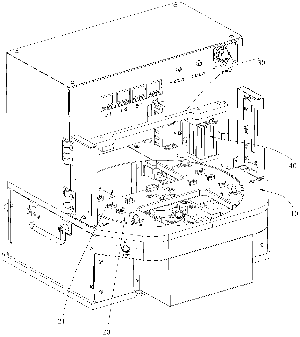
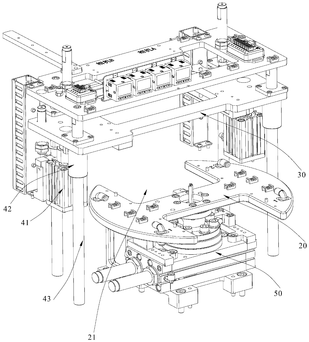
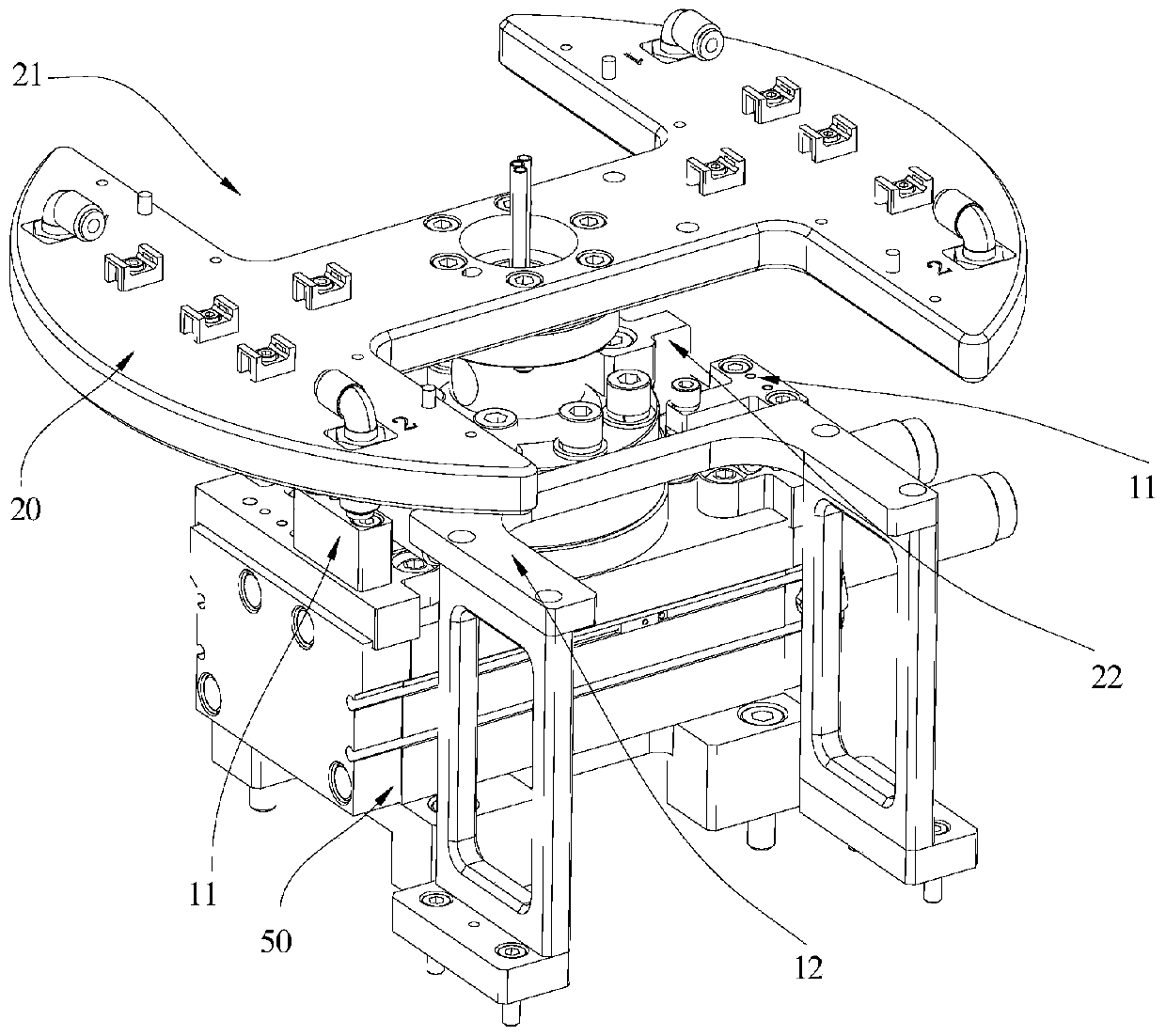
[0023] Such as Figure 1-4 The shown tooling for press-fit testing includes a body 10, a mounting frame 30, a turntable 20, a mounting frame driving mechanism 40, and a rotating disk driving mechanism 50. The mounting frame 30 is installed on the body 10, and on the mounting frame 30 The bottom end is formed as a press-fit station for mounting an external test fixture. In addition, the turntable 20 is pivotally connected to the machine body 10 , and the turntable 20 is located below the installation frame 30 . A positioning station is provided on the turntable 20, and the positioning station is used for installing an external positioning fixture. The mounting frame driving mechanism 40 can drive the mounting frame 30 to move along the height direction of the machine body 10 , and the turntable driving mechanism 50 can drive the turntable 20 to rotate....
PUM
 Abstract
Description
Claims
Application Information
 - R&D
- Intellectual Property
- Life Sciences
- Materials
- Tech Scout
- Unparalleled Data Quality
- Higher Quality Content
- 60% Fewer Hallucinations
Browse by: Latest US Patents, China's latest patents, Technical Efficacy Thesaurus, Application Domain, Technology Topic, Popular Technical Reports.
© 2025 PatSnap. All rights reserved.Legal|Privacy policy|Modern Slavery Act Transparency Statement|Sitemap|About US| Contact US: help@patsnap.com