
Band elimination filter and combiner

A band-stop filter and combiner technology, applied in the field of filters, can solve problems such as difficulty in meeting the low cost of products, low intermodulation requirements, complex assembly process, and many solder joints or screws.

Pending Publication Date: 2020-04-14
COMBA TELECOM TECH (GUANGZHOU) CO LTD
View PDF0 Cites 1 Cited by
  • Summary
  • Abstract
  • Description
  • Claims
  • Application Information

AI Technical Summary

Problems solved by technology

In a traditional combiner with a band-stop filter, the welding connection of the main channel feeder used to connect the input terminal connector and the output terminal connector has multiple coupling branches. When there are many coupling branches, the included solder joints or There are many screws and the assembly process is complicated, which makes it difficult to meet the requirements of low cost and low intermodulation

Method used


Image

  • Band elimination filter and combiner
  • Band elimination filter and combiner
  • Band elimination filter and combiner

Examples


Embodiment Construction

[0025] In order to make the above objects, features and advantages of the present invention more comprehensible, specific implementations of the present invention will be described in detail below in conjunction with the accompanying drawings. In the following description, numerous specific details are set forth in order to provide a thorough understanding of the present invention. However, the present invention can be implemented in many other ways different from those described here, and those skilled in the art can make similar improvements without departing from the connotation of the present invention, so the present invention is not limited by the specific embodiments disclosed below.

[0026] In the description of the present invention, it should be understood that the terms "first" and "second" are used for description purposes only, and cannot be interpreted as indicating or implying relative importance or implicitly indicating the quantity of indicated technical featu...


PUM


Abstract

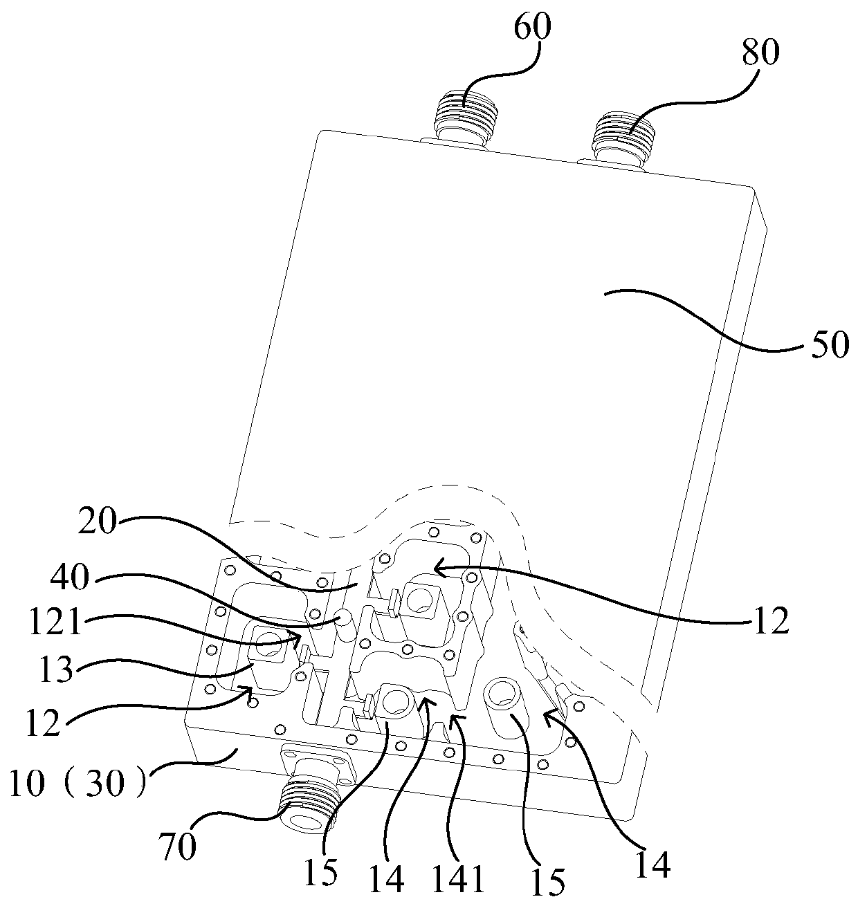
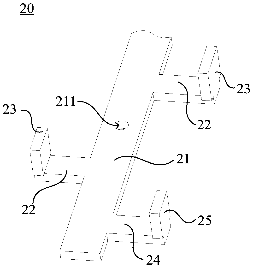
The invention relates to a band elimination filter and a combiner. The band elimination filter comprises a metal cavity, a coupling feed piece, a metal layer, an insulating support piece and a cover plate. The coupling feed piece comprises a main feed piece, a plurality of first connecting pieces and a plurality of first coupling feed plates. The other end of each first connecting piece is correspondingly connected with each first coupling feed plate, and the other end of each first connecting piece extends into a first resonant cavity through a notch. The first coupling feed plates and firstresonance columns are arranged at an interval. The main feed piece, the first connecting pieces and the first coupling feed plates are an integrated structure. The coupling feed piece is isolated fromthe metal layer through the insulating support piece, and the cover plate covers the metal cavity. As the main feed piece, the first connecting pieces and the first coupling feed plates are the integrated structure, a traditional mode of welding and connecting the main feed piece, the first connecting pieces and the first coupling feed plates is not needed, the number of welding spots can be reduced, the structure is simplified, cost is low, assembling is simple, and production efficiency is higher.

Description

technical field [0001] The invention relates to the technical field of filters, in particular to a band rejection filter and a combiner. Background technique [0002] In order to pursue resource sharing, low system cost, small device size and light weight, multiple systems and multiple frequency bands share one antenna feeder system is widely used. The improvement of multi-system and multi-band splitting and combining technology has also become an important part of the development of communication technology. In a traditional combiner with a band-stop filter, the welding connection of the main channel feeder used to connect the input terminal connector and the output terminal connector has multiple coupling branches. When there are many coupling branches, the included solder joints or There are many screws and the assembly process is complicated, which makes it difficult to meet the requirements of low cost and low intermodulation. Contents of the invention [0003] Base...

Claims


Application Information

Patent Timeline
Patent Type & Authority Applications(China)
IPC IPC(8): H01P1/208H01P1/213
CPCH01P1/208H01P1/2138
Inventor 罗贵文郭春波孟弼慧马浩军陈凯陈嘉元
Owner COMBA TELECOM TECH (GUANGZHOU) CO LTD
Learn More