Small generator

A generator, a small technology, applied in the direction of electrical components, electromechanical devices, etc., can solve the problems of unfavorable transmitter waterproof performance, short current duration, environmental protection pressure, etc., to improve market competitiveness, compact size, and improve power generation capacity Effect

Inactive Publication Date: 2020-04-14
梁惠兰
View PDF0 Cites 0 Cited by
  • Summary
  • Abstract
  • Description
  • Claims
  • Application Information

AI Technical Summary

Problems solved by technology

However, the voltage generated by piezoelectric ceramics is high and the current duration is extremely short, which makes it difficult to power the circuit.
[0003] In particular, the transmitters of the remote control exit buttons currently on the market need battery power. Since the batteries need to be replaced every once in a while, this will lead to an increase in use costs and a decrease in convenience, which is not conducive to the improvement of the waterproof performance of the transmitter. And because the battery is replaced and discarded, it will cause a certain pressure on environmental protection.

Method used


Image

  • Small generator
  • Small generator
  • Small generator

Examples


Embodiment Construction

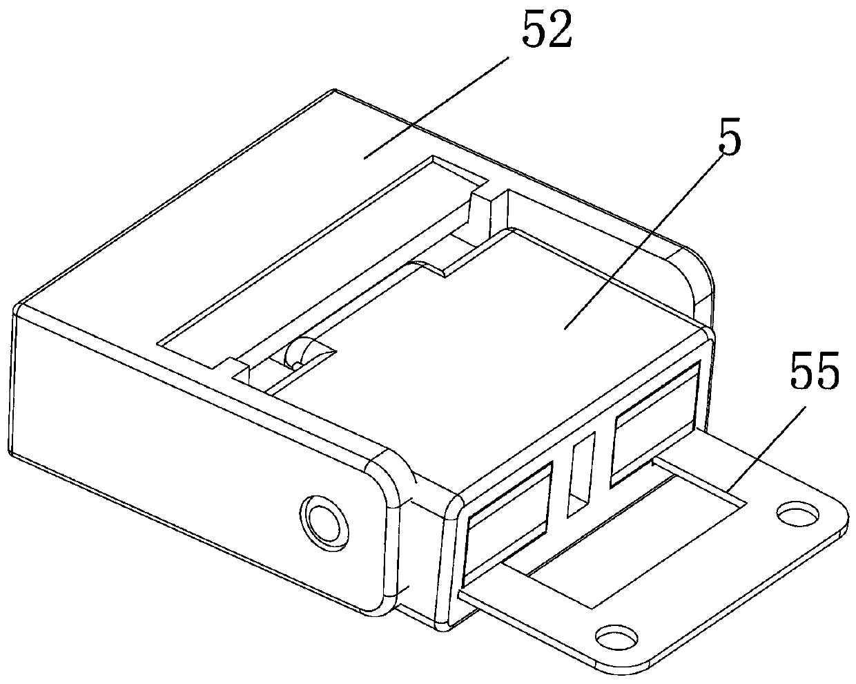
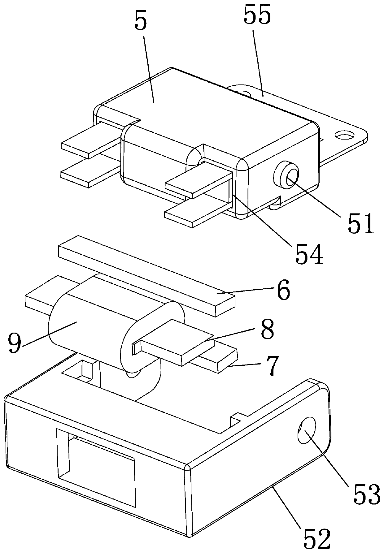
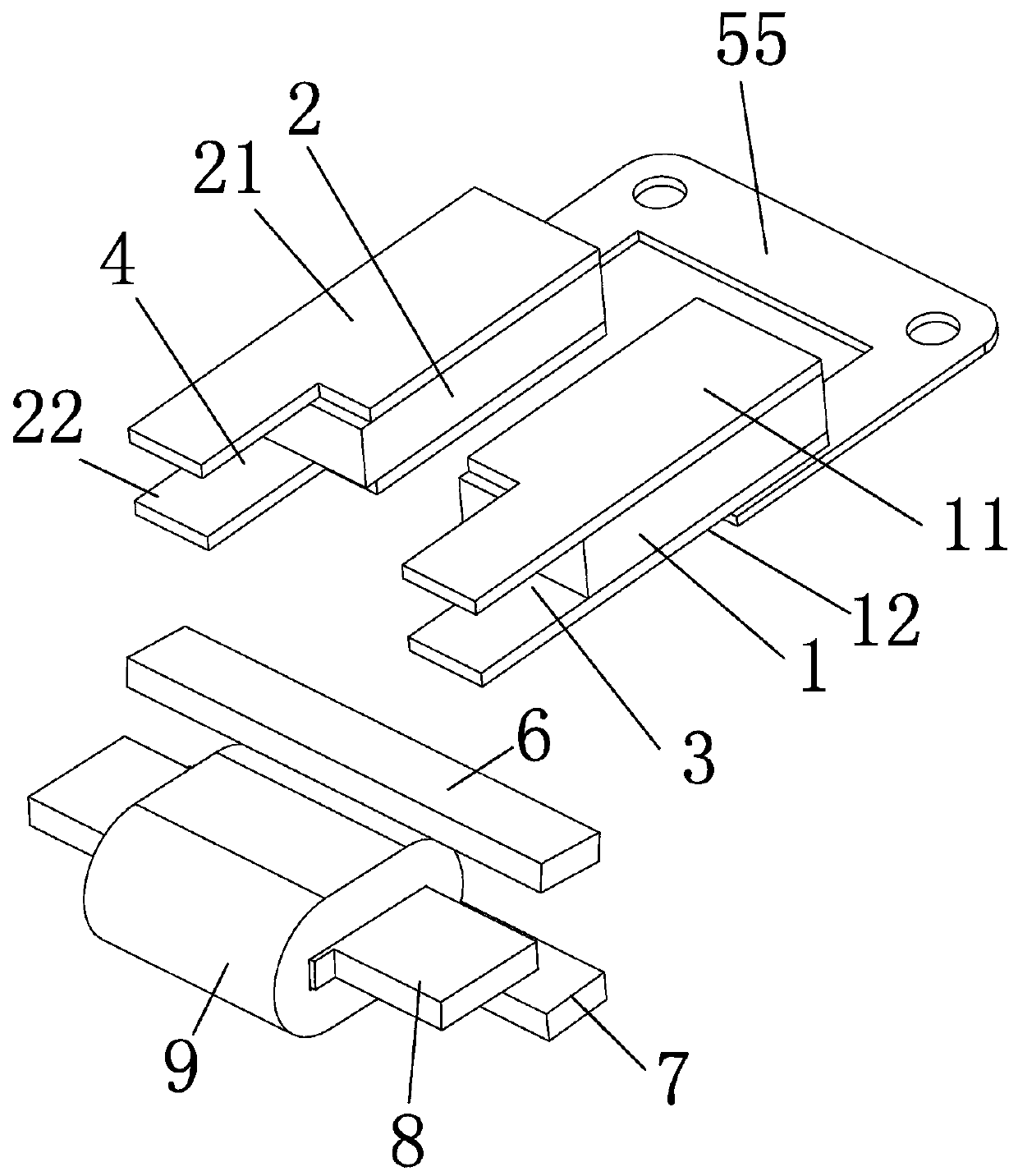
[0019] The present invention will be specifically and further described below in conjunction with the accompanying drawings. A small generator, characterized in that it includes a first permanent magnet 1 and a second permanent magnet 2, and a first magnetically conductive sheet 11 and a second magnetically conductive sheet 12 are respectively installed on the upper and lower surfaces of the first permanent magnet 1 , the upper and lower surfaces of the second permanent magnet 2 are equipped with a third magnetically conductive sheet 21 and a fourth magnetically conductive sheet 22, and the above four magnetically conductive sheets extend out of the end face of the permanent magnet. 12 forms the first limiting area 3, forms the second limiting area 4 between the third magnetically permeable sheet 21 and the fourth magnetically permeable sheet 22; the first permanent magnet 1 and the second permanent magnet 2 are oppositely fixedly arranged in On the swing frame 5; also include...


PUM


Abstract

The invention relates to a small generator, and the small generator is characterized by comprising a first permanent magnet and a second permanent magnet. A first magnetic conductive sheet and a second magnetic conductive sheet are respectively mounted on the upper and lower surfaces of the first permanent magnet; a third magnetic conductive sheet and a fourth magnetic conductive sheet are installed on the upper surface and the lower surface of the second permanent magnet, the four magnetic conductive sheets extend out of the end face of the permanent magnet, a first limiting area is formed between the first magnetic conductive sheet and the second magnetic conductive sheet, and a second limiting area is formed between the third magnetic conductive sheet and the fourth magnetic conductivesheet. The beneficial effects of the small generator are that the magnetic conductive sheets are in alternate contact with the power generation sheets, the upper connecting sheets and the lower connecting sheets, thereby changing the direction of a magnetic field entering a power generation coil, generating an induction current in the power generation coil, achieving the purpose of power generation, and being simple in operation and small in size.

Description

technical field [0001] The invention relates to a power generation device, in particular to a small power generator. Background technique [0002] Existing power generation devices are mainly generators, which are relatively large in size, and most of them generate electric energy through the high-speed rotation of the rotor, resulting in many limitations in use, so that they cannot be widely used. Piezoelectric ceramic power supply has the advantages of small size and simple power generation process, and has been used in daily life, such as lighters, stove igniters and other equipment. However, piezoelectric ceramics generate high voltages and extremely short current durations, making it difficult to power circuits. [0003] In particular, the transmitters of the remote control exit buttons currently on the market need battery power. Since the batteries need to be replaced every once in a while, this will lead to an increase in use costs and a decrease in convenience, whic...

Claims


Application Information

Patent Timeline
IPC IPC(8): H02K35/02
CPCH02K35/02
Inventor 梁惠兰
Owner 梁惠兰
Why Eureka
Try Eureka