Light-load frequency reduction circuit of charge pump based on current control

A current control and charge pump technology, which is applied to emergency protection circuit devices, conversion equipment without intermediate conversion to AC, electrical components, etc., can solve problems such as low reliability and low efficiency of light-load frequency reduction, and achieve reliability assurance , Ensure reliability and stability, and avoid the effect of large instantaneous current

Active Publication Date: 2020-04-14
SOUTHCHIP SEMICON TECH SHANGHAI CO LTD
View PDF5 Cites 1 Cited by
  • Summary
  • Abstract
  • Description
  • Claims
  • Application Information

AI Technical Summary

Problems solved by technology

[0009] The purpose of the present invention is to provide a light-load frequency reduction circuit based on a current-controlled charge ...

Method used


Image

  • Light-load frequency reduction circuit of charge pump based on current control
  • Light-load frequency reduction circuit of charge pump based on current control
  • Light-load frequency reduction circuit of charge pump based on current control

Examples


Embodiment

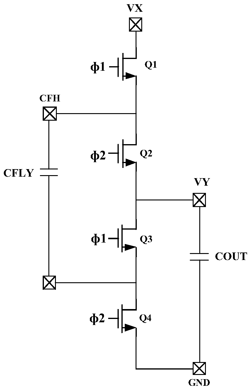
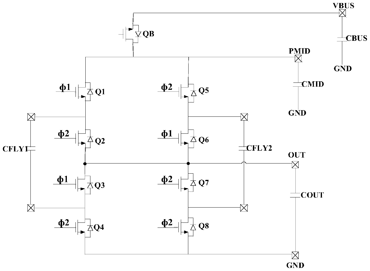
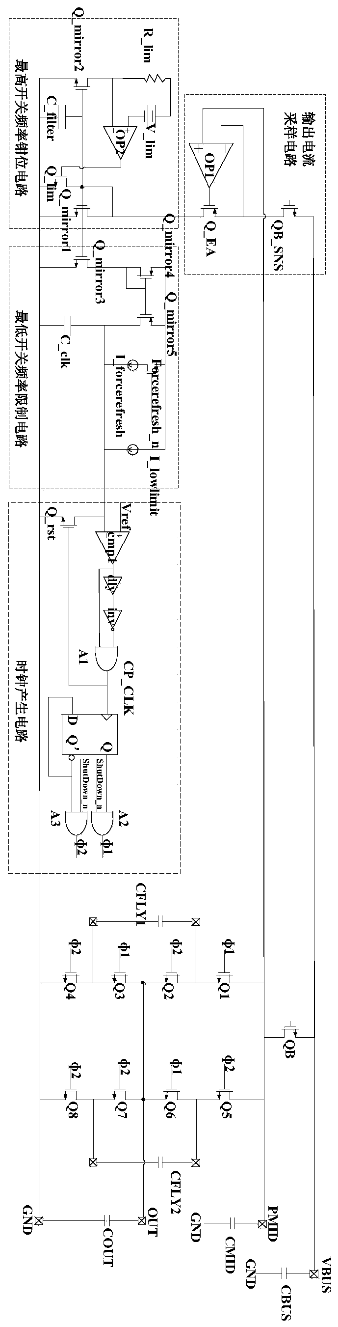
[0030] Such as Figure 3-5 As shown, a light-load frequency reduction circuit based on a current-controlled charge pump disclosed in the present invention includes an output current sampling circuit connected to the charge pump circuit, a maximum switching frequency clamp circuit connected to the output current sampling circuit, and the highest The minimum switching frequency limiting circuit connected with the switching frequency clamping circuit, and the clock generating circuit connected with both the minimum switching frequency limiting circuit and the charge pump circuit.

[0031]The light-load frequency reduction circuit also includes a pressure difference monitoring circuit and an extreme pressure difference protection circuit both connected to the charge pump circuit.

[0032] The current sampling circuit includes a sampling tube QB_SNS whose source is connected to the power input terminal VBUS of the charge pump circuit, a MOS transistor Q_EA whose source is connected...


PUM


Abstract

The invention discloses a light-load frequency reduction circuit of a charge pump based on current control. Problems that an existing charge pump circuit is low in light-load frequency reduction efficiency and low in reliability are mainly solved. The light-load frequency reduction circuit comprises an output current sampling circuit connected with a charge pump circuit, a highest switching frequency clamping circuit connected with the output current sampling circuit, a lowest switching frequency limiting circuit connected with the highest switching frequency clamping circuit, and a clock generation circuit connected with the lowest switching frequency limiting circuit and the charge pump circuit. In the invention, a reverse blocking tube QB of an original charge pump system is utilized togenerate a clock linearly related to an output load so that conversion efficiency of the charge pump can be kept high under a light load. And a lag problem of a clock frequency is adjusted by using an average current so that safety and reliability of the system under extreme conditions such as an abrupt change of a power supply/a load, even capacitor open-short circuit/input-output instantaneousshort ground and the like are ensured. Therefore, the circuit is suitable for popularization and application.

Description

technical field [0001] The invention relates to the technical field of charge pumps, in particular to a light-load frequency reduction circuit based on a current-controlled charge pump. Background technique [0002] Charge pumps are switching converters that use capacitors to store energy, where switches are used to switch the capacitors between supply and discharge states, thereby raising or lowering the supply voltage. In mobile terminals or portable electronic devices, the voltage of the power supply may be lower than the operating voltage, and the charge pump can provide the voltage of the power supply to work after the system, for example, the voltage generated by the charge pump is in the range of 3.3V to 4.0V, so as to meet Electronic equipment needs to work. [0003] Such as figure 1 The circuit schematic diagram of the charge pump is shown, the four power tubes are divided into two phases Φ1 and Φ2, and they are turned on respectively. Under the ideal condition of...

Claims


Application Information

Patent Timeline
IPC IPC(8): H02M3/07H02M1/32H02H7/12
CPCH02H7/1213H02M1/32H02M3/07
Inventor 马俊
Owner SOUTHCHIP SEMICON TECH SHANGHAI CO LTD
Why Eureka
Try Eureka