LED lamp bead fixing method, LED lamp strip and mobile terminal

A technology of LED lamp beads and LED lamp strips, applied in the field of backlight source, can solve the problem that LED lamp strips cannot meet the performance requirements of thrust test, and achieve the effects of improving fixing reliability, increasing red glue bonding, and improving anti-thrust performance.

Active Publication Date: 2020-04-14
SHENZHEN SOUTH POLE OPTOELECTRONICS TECH
View PDF11 Cites 6 Cited by
  • Summary
  • Abstract
  • Description
  • Claims
  • Application Information

AI Technical Summary

Problems solved by technology

[0006] Based on this, it is necessary to address the above-mentioned technical problems and provide a method for fixing at least one LED lamp bead, an LED lamp strip and a mobile terminal, aiming to improve the LED lamp strips assembled through the technological process in the prior art that cannot meet the requirements. Questions about Thrust Test Performance Requirements

Method used


Image

  • LED lamp bead fixing method, LED lamp strip and mobile terminal

Examples


Embodiment Construction

[0039] In order to make the object, technical solution and advantages of the present invention clearer, the present invention will be further described in detail below in conjunction with the accompanying drawings and embodiments. It should be understood that the specific embodiments described here are only used to explain the present invention, not to limit the present invention.

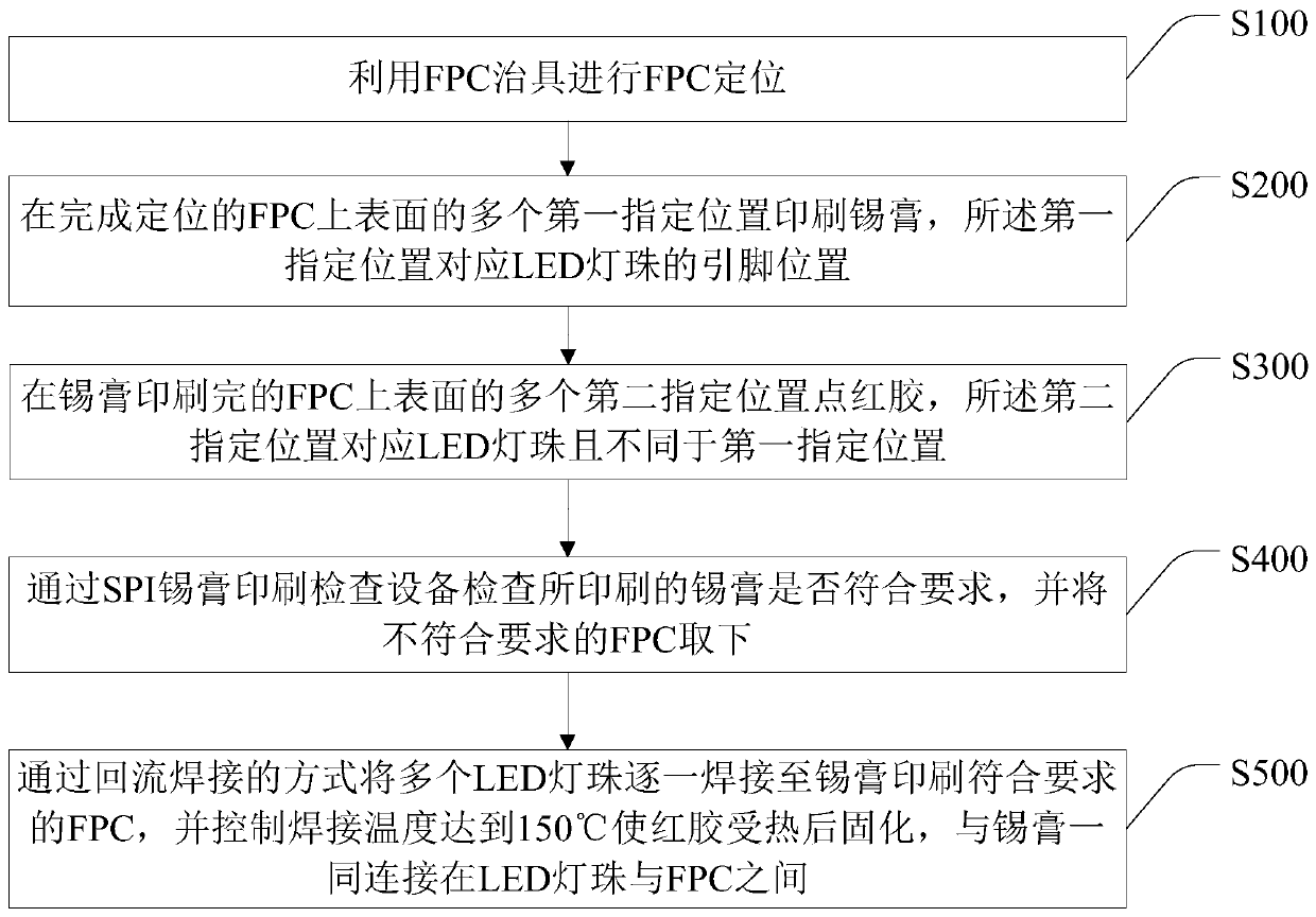
[0040] Such as figure 1 As shown, the present invention provides a method for fixing LED lamp beads, which includes the steps of:

[0041] S100, using the FPC jig to perform FPC positioning.

[0042] S200. Print solder paste on a plurality of first designated positions on the upper surface of the positioned FPC, where the first designated positions correspond to pin positions of LED lamp beads.

[0043] S300. Apply red glue to a plurality of second designated positions on the upper surface of the FPC after the solder paste has been printed, the second designated positions correspond to LED lamp b...


PUM


Abstract

The invention relates to an LED lamp bead fixing method, an LED lamp strip and a mobile terminal. The LED lamp bead fixing method comprises the steps of carrying out FPC positioning through an FPC jig; printing a solder paste at a plurality of first specified positions on an upper surface of the FPC; dispensing a red glue at a plurality of second designated positions on the upper surface of the FPC printed with the solder paste; detecting whether the printed solder paste meets a requirement or not through SPI solder paste printing checking equipment; and welding multiple LED lamp beads to theFPC one by one through reflow soldering, and making a welding temperature reach 150 DEG C so that the red glue is cured after being heated. By using the LED lamp bead fixing method, a process of dispensing the red glue is added, and the welding temperature is controlled to reach 150 DEG C so that the red glue can be immediately cured after being heated, the LED lamp beads and the FPC which are originally welded together only through the solder paste are bonded through the red glue, fixing reliability of the LED lamp beads on the LED lamp strip is improved, and anti-push performance of the LEDlamp beads is increased.

Description

technical field [0001] The invention relates to the technical field of backlight sources, in particular to a method for fixing LED lamp beads, an LED lamp strip and a mobile terminal. Background technique [0002] The backlight (Back Light) is a light source located behind the liquid crystal display (LCD), and its luminous effect will directly affect the visual effect of the liquid crystal display module (LCM). Backlight is widely used in touch screen, LCD / LCM, mobile phone, tablet computer, GPS and solar cell and other industries; it is mainly composed of light source, light guide plate, optical module and structural parts; among them, the light source mainly includes EL, CCFL and LED Types of backlight sources; light guide plates are divided into printing, chemical etching (Etching), precision mechanical characterization (V-cut), light lithography (Stamper), internal diffusion, hot pressing; optical modules: enhancement film / sheet, Diffusion film / sheet, reflection sheet, ...

Claims


Application Information

Patent Timeline
Patent Type & Authority Applications(China)
IPC IPC(8): H05K3/00H05K3/34H05K13/08G02F1/13357
CPCH05K3/0008H05K3/341H05K3/3457H05K13/0817G02F1/133603
Inventor 徐贤强李庭姜发明
Owner SHENZHEN SOUTH POLE OPTOELECTRONICS TECH
Why Eureka
Try Eureka