
A cable pay-off and cutting equipment for municipal engineering

A cutting equipment and engineering technology, used in the field of cable pay-off cutting equipment, can solve the problems of slow cutting speed, easy to bounce, large cable diameter, etc., to achieve the effect of easy to cut the cable, small contact area, and increase the surface roughness.

Active Publication Date: 2021-06-15
山东宏远电力科技有限公司
View PDF7 Cites 0 Cited by
  • Summary
  • Abstract
  • Description
  • Claims
  • Application Information

AI Technical Summary

Problems solved by technology

[0002] The cable is made of one or more mutually insulated conductors and an outer insulating protective layer. It is mainly used for power transmission. At present, as the length of the cable used in municipal engineering is long, the speed of manual pulling and cutting is slow and the efficiency is low. Because the diameter of the cables used in municipal projects is large, it is easy to bounce out and cause safety problems

Method used


Image

  • A cable pay-off and cutting equipment for municipal engineering
  • A cable pay-off and cutting equipment for municipal engineering
  • A cable pay-off and cutting equipment for municipal engineering

Examples


Embodiment 1

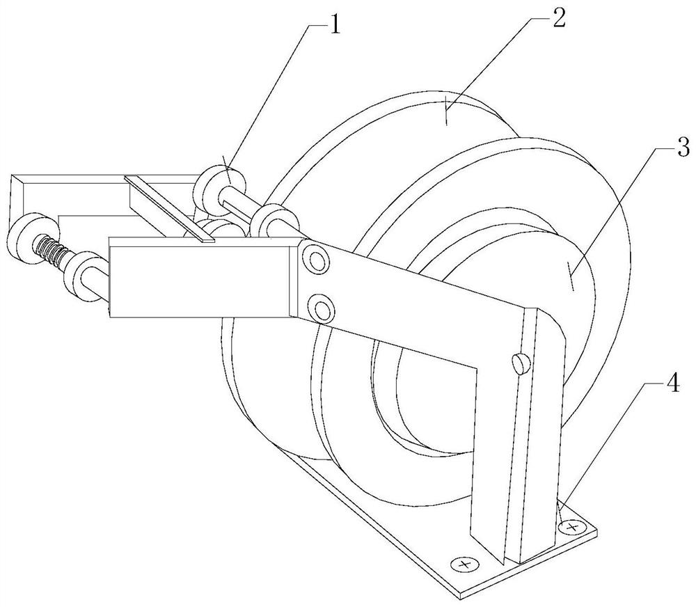
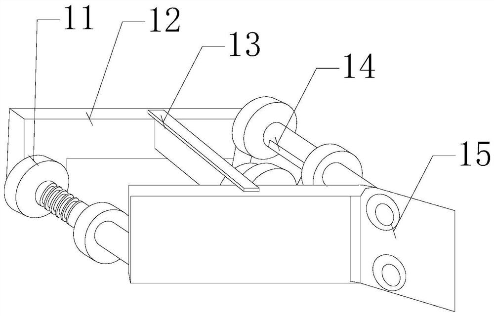
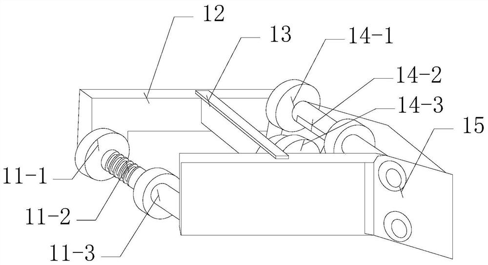
[0026] see Figure 1-Figure 3 , a kind of cable pay-off and cutting equipment for municipal engineering, the present invention provides a kind of cable pay-off and cutting equipment for municipal engineering. The above chassis 4 is provided with winding reel 2, and described winding reel 2 is fixed on the chassis 4 by fixed shaft 3, and the left side of described chassis 4 is equipped with pay-off cutting structure 1, and described pay-off and cutting structure 1 A first fixed frame 11, a first frame plate 12, a press-cut structure 13, a second fixed frame 14, and a second frame plate 15 are provided. The second frame plate 15 and the first frame plate 12 are parallel to each other, and the two are A press-cutting structure 13 is arranged in the middle, and the left and right sides of the press-cutting structure 13 are respectively provided with a first fixing frame 11 and a second fixing frame 14, and the front and rear ends of the first fixing frame 11 and the second fixing ...

Embodiment 2

[0033] see Figure 1-Figure 5, a kind of cable pay-off and cutting equipment for municipal engineering, the present invention provides a kind of cable pay-off and cutting equipment for municipal engineering. The above chassis 4 is provided with winding reel 2, and described winding reel 2 is fixed on the chassis 4 by fixed shaft 3, and the left side of described chassis 4 is equipped with pay-off cutting structure 1, and described pay-off and cutting structure 1 A first fixed frame 11, a first frame plate 12, a press-cut structure 13, a second fixed frame 14, and a second frame plate 15 are provided. The second frame plate 15 and the first frame plate 12 are parallel to each other, and the two are A press-cutting structure 13 is arranged in the middle, and the left and right sides of the press-cutting structure 13 are respectively provided with a first fixing frame 11 and a second fixing frame 14, and the front and rear ends of the first fixing frame 11 and the second fixing f...


PUM


Abstract

The invention discloses a cable pay-off and cutting device for municipal engineering. The structure comprises a pay-off and cutting structure, a wire reel, a fixed shaft and a chassis. A wire reel is arranged directly above the chassis and is fixed on the On the chassis, an unwinding cutting structure is installed on the left side of the chassis, and the unwinding and cutting structure is provided with a first fixing frame, a first shelf plate, a press-cutting structure, a second fixing frame, a second shelf plate, a second shelf plate and a second shelf plate. A frame plate is parallel to each other. The present invention uses the design of the annular groove on the first fixed frame. When the cable passes through, it will not slide relative to each other instantaneously and requires external force assistance. The cable will not automatically spring outwards. Through the mutual cooperation between the movable knife and the spring, the present invention uses the spring and the movable knife to continuously press down on the passing cable. The movable knife is a structure with a wide top and a narrow bottom. When the contact area is small, it is easier to cut the cable.

Description

technical field [0001] The invention relates to the field of municipal engineering, in particular to a cable pay-off and cutting device for municipal engineering. Background technique [0002] The cable is made of one or more mutually insulated conductors and an outer insulating protective layer. It is mainly used for power transmission. At present, as the length of the cable used in municipal engineering is long, the speed of manual pulling and cutting is slow and the efficiency is low. Because the diameter of the cables used in municipal engineering is relatively large, it is also easy to bounce out and cause safety problems. Contents of the invention [0003] Aiming at the deficiencies of the prior art, the present invention is realized through the following technical solutions: a cable pay-off and cutting equipment for municipal engineering, its structure includes a pay-off and cutting structure, a winding reel, a fixed shaft, and a chassis, and the chassis A winding ...

Claims


Application Information

Patent Timeline
Patent Type & Authority Patents(China)
IPC IPC(8): B21F11/00B21F23/00
CPCB21F11/00B21F23/00
Inventor 苏少珊毕桂有
Owner 山东宏远电力科技有限公司
Learn More