A batch screw automatic dismantling machine

A technology of automatic disassembly and screwing, which is applied in the direction of metal processing equipment, metal processing, manufacturing tools, etc., can solve the problems of less manual operation, high labor load, frequent manual control operations, etc., and achieve the effect of ensuring the continuity of work

Active Publication Date: 2021-09-24
SUZHOU PULUN ELECTRONICS TECH CO LTD
View PDF0 Cites 0 Cited by
  • Summary
  • Abstract
  • Description
  • Claims
  • Application Information

AI Technical Summary

Problems solved by technology

[0005] In order to overcome the shortcomings of high labor, low work efficiency, and frequent manual control operations of the screw dismantling machine when dismantling a large number of screws, the technical problem to be solved is to provide a machine that can dismantle a large number of workpieces, has high work efficiency, and is manually operated. Small amount of batch screw automatic dismantling machine

Method used


Image

  • A batch screw automatic dismantling machine
  • A batch screw automatic dismantling machine
  • A batch screw automatic dismantling machine

Examples


Embodiment 1

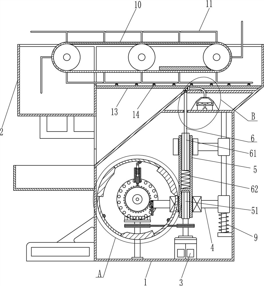
[0020] Such as figure 1 , 2 , 4, a batch screw automatic disassembly machine, including an organic casing 1, a collection frame 2, a motor 3 and a slide bar 4, the top left side of the casing 1 is provided with a collection frame 2, the connection between the collection frame 2 and the casing 1 They are connected by bolts, the motor 3 is installed at the inner bottom of the casing 1, and the sliding rod 4 is installed on the right side of the casing 1, and the sliding rod 4 is horizontally arranged, and also includes an inner rhombic tube 5, a second A diamond-shaped rod 51, tension spring 9, conveyor belt 10, connecting plate 11, rotating assembly 6, transmission starting assembly 7 and upward moving assembly 8, the rotating type on the slide bar 4 is provided with an inner diamond-shaped pipe 5, and the inner diamond-shaped The tube 5 is rotatably connected to the sliding rod 4 by means of a bearing seat connection, the inner diamond-shaped tube 5 is perpendicular to the sl...

Embodiment 2

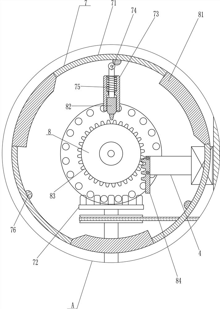
[0023] On the basis of Example 1, such as figure 1 and image 3 As shown, the rotating assembly 6 includes a second rhombic rod 61, an elastic member 62, a screwdriver 63, and the inner upper part of the inner rhombic tube 5 is slidably fitted with the second rhomboid rod 61, and the second rhomboid rod 61 is connected to the inner rhombic shape. An elastic member 62 is connected between the inner walls of the tube 5, and a screwdriver 63 is connected to the top of the second rhombic rod 61. The screwdriver 63 is connected to the second rhomboid rod 61 in a detachable manner, and the screwdriver 63 is located between the front and rear connecting plates 11. Below the space, there is an opening in the middle part on the left side of the casing 1, and the opening is used to discharge the disassembled bolts.

[0024] The rotation of the inner diamond tube 5 drives the second rhombus rod 61 to rotate, so that the screwdriver 63 can be rotated quickly to disassemble the screw. Whe...

Embodiment 3

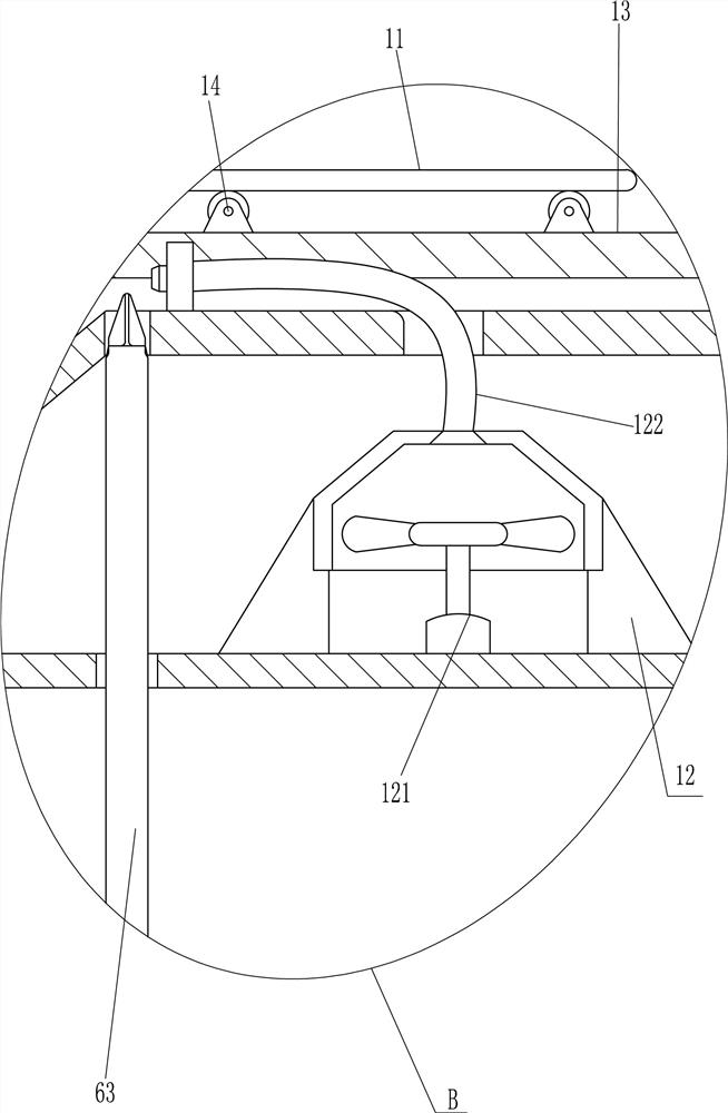
[0030] On the basis of Example 2, such as image 3 As shown, a blower assembly 12 is also included, and the blower assembly 12 includes a blower 121 and a ventilation pipe 122. A blower 121 is installed on the right side of the upper part of the casing 1, and a blower 121 is connected to a ventilation pipe 122 at the blower outlet. The ventilation pipe 122 is located in the screwdriver. 63 top right.

[0031] Start the blower 121 to rotate, so that the wind is blown out through the air vent. When the screwdriver 63 resets downward, the wind will blow off the screws on the screwdriver 63, so that the screws roll off to the outside of the casing 1. In this way, the screws can be prevented from being attached all the time. On the screwdriver 63, the effect of ensuring the continuity of work.

[0032] Such as figure 1 , 3 As shown, it also includes a fixed plate 13 and a support wheel 14. The upper, front and rear sides of the casing 1 are symmetrically provided with a fixed pl...


PUM


Abstract

The invention relates to a screw removal machine, in particular to an automatic batch screw removal machine. The technical problem to be solved is how to design a batch screw automatic dismounting machine that can disassemble a large number of workpieces, has high work efficiency, and has a small amount of manual operation. A batch screw automatic dismantling machine, including an organic casing, a collection frame, a motor, a sliding rod, an inner diamond tube, a first rhombus rod, a tension spring, a conveyor belt, etc.; the top left side of the casing is provided with a collection frame, A motor is installed at the inner bottom of the casing, a sliding rod is installed on the right side of the casing, and an inner diamond-shaped tube is arranged on the sliding rod. The type rod is connected with the output shaft of the motor, a tension spring is connected between the sliding rod and the casing, and a conveyor belt is installed on the inner top of the casing. The invention achieves the effect that the screw can be automatically disassembled by moving the rotating component upward to disassemble the screw by moving the component upward.

Description

technical field [0001] The invention relates to a screw removal machine, in particular to an automatic batch screw removal machine. Background technique [0002] In the development of modern industry, the assembly line is the only way for the production of product workpieces, and the disassembly and assembly of screws is also an important process of the assembly line of workpiece products, so there will be a large number of products in the workpiece products that need to remove the fixing screws. Some semi-finished products and reworked products, and these defective products need to be disassembled for maintenance and utilization. [0003] At present, when using a screw dismantling machine on the market to disassemble a screw, first put the workpiece on a fixed disassembly plate, then control the screw dismantling machine to move down to the screw hole groove to dismantle the screw, and then control the screw dismantling machine to move or reset, disassemble Afterwards, the...

Claims


Application Information

Patent Timeline
Patent Type & Authority Patents(China)
IPC IPC(8): B23P19/06
CPCB23P19/06
Inventor 郑晓璇
Owner SUZHOU PULUN ELECTRONICS TECH CO LTD
Why Eureka
Try Eureka