A wood grinding device
A technology for wood and grinding mechanism, applied in the field of wood processing, can solve problems such as being unsuitable for small wood processing plants, unusable logs, large size, etc., and achieve the effects of saving manpower, saving costs, and avoiding manual handling
- Summary
- Abstract
- Description
- Claims
- Application Information
AI Technical Summary
Problems solved by technology
Method used
Image

Examples
specific Embodiment approach 1
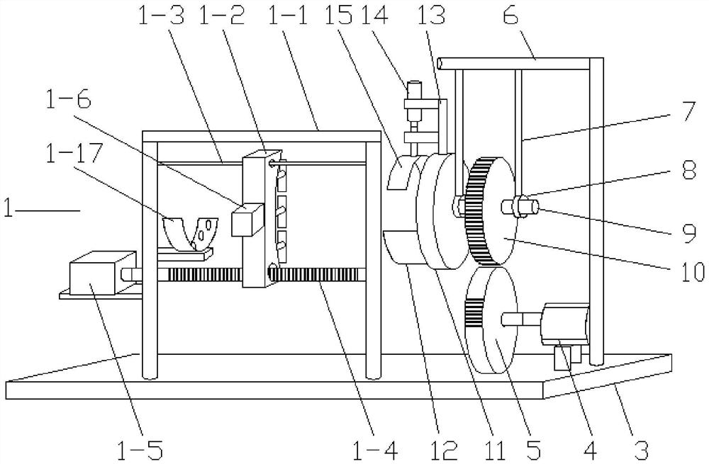
[0020] Combine below Figure 1-7 Describe this embodiment, a wood grinding device, including a grinding mechanism 1, a mobile lifting mechanism 2 and a bottom plate 3, one end of the bottom plate 3 is connected with an incomplete gear 5 through a motor 4, and also includes a cantilever beam 6, the cantilever beam 6 is connected to the bearing seat 8 through the pull rod 7, the bearing seat 8 is connected to the gear 10 through the shaft 9, one end of the shaft 9 is connected to the positioning plate 11, and the lower end of the side wall of the positioning plate 11 is connected to the arc frame I12 , the top of the positioning plate 11 is connected to the cylinder 14 through the bracket 13, and the cylinder 14 is connected to the arc frame II15.
[0021] The cantilever beam 6 is fixed on the column, and the pull rod 7 is connected with the column through multiple tie bars to ensure the stability of the pull rod 7. There are two pull rods 7 and two bearing seats 8, which are ar...
specific Embodiment approach 2
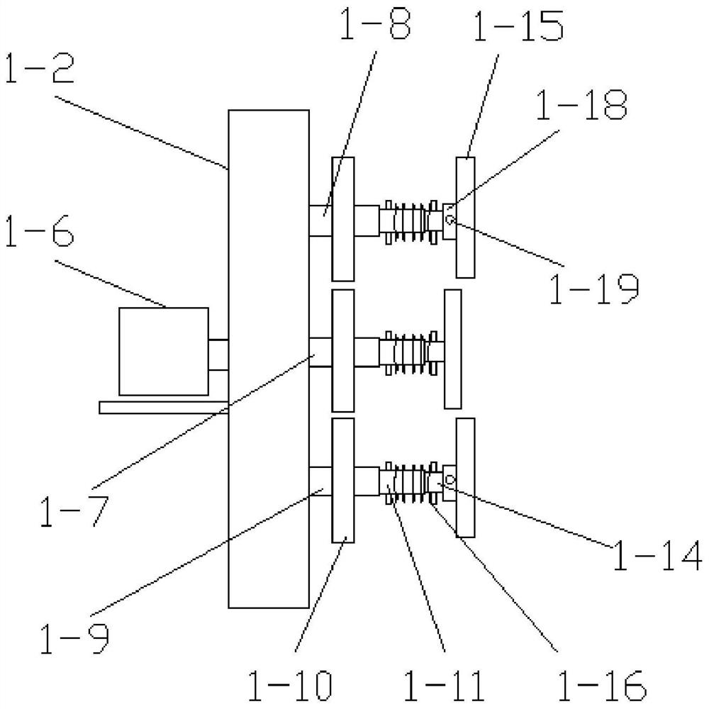
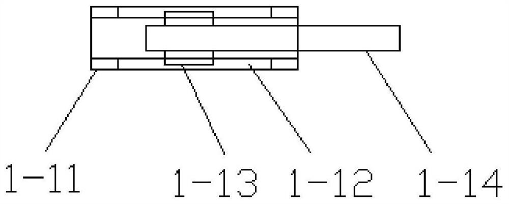
[0023] Combine below Figure 1-7 To illustrate this embodiment, the grinding mechanism 1 includes a frame 1-1 and a rectangular moving block 1-2, the upper end of the frame 1-1 is provided with a slide bar 1-3, and the rectangular moving block 1-2 The upper end of the sliding bar 1-3 is slidingly connected, and the lower end of the rectangular moving block 1-2 is provided with a threaded through hole, and the threaded through hole is provided with a screw 1-4, and the screw 1-4 is connected to the screw. The bar motors 1-5 are connected, the rectangular moving block 1-2 is provided with a moving motor 1-6, the output shaft of the moving motor 1-6 is connected with the shaft I1-7, and the upper and lower sides of the shaft I1-7 Shaft II1-8 and shaft III1-9 are arranged on both sides, said shaft I1-7, shaft II1-8 and shaft III1-9 are provided with intermeshing gears I1-10, said shaft I1-7, shaft The ends of II1-8 and III1-9 are provided with shaft tubes 1-11, and the inner wall...
specific Embodiment approach 3
[0026] Combine below Figure 1-7 To illustrate this embodiment, the mobile lifting mechanism 2 includes a base 2-1, the base 2-1 is provided with a chute 2-2, and the chute 2-2 is provided with a moving slider 2-3. The moving slider 2-3 is provided with a hydraulic cylinder 2-4, the surface of the base 2-1 is connected with the supporting plate 2-5 through a support column, and the surface of the supporting plate 2-5 is provided with a T-shaped through groove 2-6, the T-shaped through groove 2-6 is provided with a T-shaped sliding bar 2-7, the bottom end of the T-shaped sliding bar 2-7 is connected with the hydraulic cylinder 2-4, and the supporting plate 2- The edge portion of 5 is provided with threaded hole, and described threaded hole is provided with screw mandrel 2-8, and one end of described screw mandrel 2-8 is rotationally connected with T-shaped sliding bar 2-7, and described screw mandrel 2-8 The other end of 8 is connected with rocking bar 2-9, and the upper surfa...
PUM
 Abstract
Description
Claims
Application Information
 - R&D Engineer
- R&D Manager
- IP Professional
- Industry Leading Data Capabilities
- Powerful AI technology
- Patent DNA Extraction
Browse by: Latest US Patents, China's latest patents, Technical Efficacy Thesaurus, Application Domain, Technology Topic.
© 2024 PatSnap. All rights reserved.Legal|Privacy policy|Modern Slavery Act Transparency Statement|Sitemap