Auxiliary tool for installing building wall nail

An installation auxiliary and building wall technology, which is applied in the field of building wall nail installation auxiliary tools, can solve the problems of bending and the direction of the force of the nail is not straight, and achieves the effect of improving practicability and improving efficiency.

Pending Publication Date: 2020-04-17
中建河图建设有限公司
View PDF1 Cites 0 Cited by
  • Summary
  • Abstract
  • Description
  • Claims
  • Application Information

AI Technical Summary

Problems solved by technology

[0004] Based on the existing auxiliary tools for nailing, most of them cannot solve the technical problem that the nails are bent because the direction of the force is not straight. This invention proposes an auxiliary tool for the installation of building wall nails.

Method used


Image

  • Auxiliary tool for installing building wall nail
  • Auxiliary tool for installing building wall nail
  • Auxiliary tool for installing building wall nail

Examples


Embodiment 1

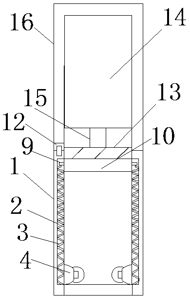
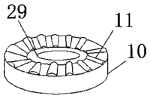
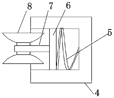
[0030] refer to Figure 1-7 , an auxiliary tool for installation of building wall nails, comprising a first cavity 1, both sides of the first cavity 1 are provided with strip-shaped grooves 2, and the first cavity 1 is welded with a second strip-shaped groove 2 A spring 3, the top of the first spring 3 is welded with a sliding block 9, one side of the sliding block 9 is welded with a mating ring 10, the top of the first cavity 1 is provided with a second cavity 16, the second An air motor 14 is welded on the inner wall of the top end of the cavity 16, an output shaft 15 is welded on the bottom end of the air motor 14, a rotating ring 13 is welded on the bottom end of the output shaft 15, and a rotating ring 13 is welded to the outside of the mating ring 10. Several arc-shaped bars 11, one side of the second cavity 16 is provided with a circular groove, and the second cavity 16 is welded with a first expansion joint 12 at the circular groove, and the inside of the first expansi...

Embodiment 2

[0039] refer to Figure 8 , an auxiliary tool for installing building wall nails. Compared with Embodiment 1, in this embodiment, in order to prevent the nail from shifting inside the first cavity, the bottom end of the curved block 26 is welded with a rubber layer 30, and the rubber layer 30 One side is provided with an anti-slip pattern 31, when the nail and the curved block 26 collide with each other, the anti-slip pattern 31 increases the friction with the top of the nail, prevents the nail from shifting inside the first cavity 1, and improves the stability of the nail .

[0040] When in use, by turning on the air motor 14, the air motor 14 drives the rotating ring 13 and the arc-shaped bar 11 on the matching ring 10 to squeeze each other, the first spring 3 keeps reciprocating, and knocks the matching ring 10 by constantly squeezing, the matching ring 10 drives the inner ring 29 to knock the front end of the nail continuously, so that the nail is continuously nailed into...


PUM


Abstract

The invention belongs to the technical field of building equipment, and particularly discloses an auxiliary tool for installing a building wall nail. Since most of existing nailing auxiliary tools cannot solve the technical problem that a nail is bent as the force bearing direction is not upright, the scheme is now put forward. The auxiliary tool for installing the building wall nail comprises a first cavity. The two sides of the first cavity are each provided with a strip-shaped groove. The strip-shaped grooves of the first cavity are fixedly connected with first springs. The top ends of thefirst springs are fixedly connected with sliders. One sides of the sliders are fixedly connected with a matched ring. The top end of the first cavity is provided with a second cavity. The inner wall of the top end of the second cavity is fixedly connected with a pneumatic motor. The bottom end of the pneumatic motor is fixedly connected with an output shaft. The bottom end of the output shaft is fixedly connected with a rotating ring. The outer portion of one side of the rotating ring and the outer portion of one side of the matched ring are fixedly connected with arc-shaped strips. In he auxiliary tool, through the extrusion of the matched ring and the rotating ring, the nail is driven to be nailed into a wall surface, efficiency is improved, and meanwhile it is avoided that a nail body of the nail is bent as the force bearing direction is not consistent with the direction of the nail body.

Description

technical field [0001] The invention relates to the technical field of building equipment, in particular to an auxiliary tool for installing building wall nails. Background technique [0002] In our daily life, we often need to use nails for various places in construction projects. However, when nailing nails to the wall, we usually hold the nails in one hand and hammer in the other, and nail the nails to the wall by tapping. On the other hand, most of the existing nailing auxiliary tools still need to be nailed manually with a hammer. When nailing, the direction of the force used is deflected, which may cause the nail to bend. [0003] After retrieval, the Chinese patent application number is CN201811420993.2, which discloses a clamping device, especially a clamping device for nailing nails. The technical problem to be solved is to provide a nail that can be clamped to facilitate people to nail. The nailing device does not need to be held by hand to avoid being knocked, an...

Claims


Application Information

Patent Timeline
IPC IPC(8): B25C3/00B25C7/00
CPCB25C3/00B25C7/00
Inventor 王凡钱光华林少龙徐盖陈子杰陈登意张敏
Owner 中建河图建设有限公司
Why Eureka
Try Eureka