Sightseeing cabin mounting and connecting structure, sightseeing cabin applying sightseeing cabin mounting and connecting structure and sightseeing boat

A technology for connecting structures and sightseeing cabins, which is applied to ships, underwater ships, transportation and packaging, etc., can solve problems such as easy safety problems, and achieve the effects of high space utilization, wide use and wide viewing field.

Pending Publication Date: 2020-04-17
浙江横海科技有限公司
View PDF2 Cites 2 Cited by
  • Summary
  • Abstract
  • Description
  • Claims
  • Application Information

AI Technical Summary

Problems solved by technology

[0006] Although the above-mentioned patent discloses a transparent cylindrical observation cabin, the observation cabin is only connected to the floating body through the top installation cover on the top without any connection reinforcement. Under water, the buoyancy of the observation cabin is concentrated At the connection position between the observation cabin and the floating body, safety problems are very likely to occur

Method used


Image

  • Sightseeing cabin mounting and connecting structure, sightseeing cabin applying sightseeing cabin mounting and connecting structure and sightseeing boat
  • Sightseeing cabin mounting and connecting structure, sightseeing cabin applying sightseeing cabin mounting and connecting structure and sightseeing boat
  • Sightseeing cabin mounting and connecting structure, sightseeing cabin applying sightseeing cabin mounting and connecting structure and sightseeing boat

Examples


Embodiment 1

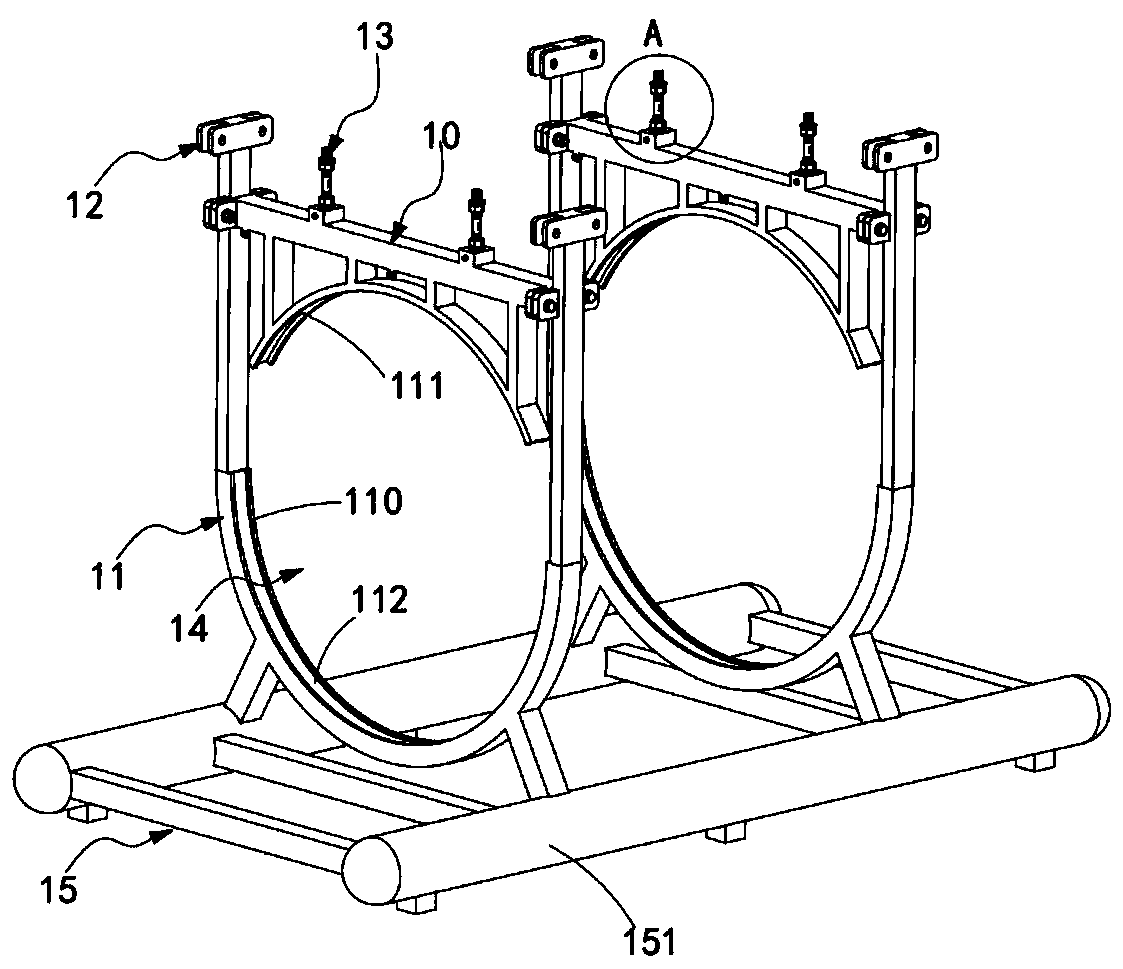
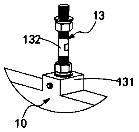
[0069] Such as Figure 1 to Figure 2 As shown, a sightseeing cabin installation connection structure includes at least one set of pressure beams 10, a connection installation frame mechanism 11 located directly below the pressure beams 10, and a structure located above the pressure beams 10 and along the length direction of the pressure beams 10. The connecting piece 12 arranged symmetrically on the center line of the pressure beam 10 is provided with two sets of pressure bearing mechanisms 13, the pressure bearing mechanisms 13 are arranged symmetrically along the center line in the length direction of the pressure beam 10, and the connection installation frame mechanism 11 is provided with an installation space 14 that is contoured to the outer wall of the sightseeing cabin and is used to surround and fix the sightseeing cabin. The lower part of the connecting piece 12 is detachably and fixedly connected to both ends of the pressure beam 10 in the longitudinal direction.

[...

Embodiment 2

[0080] Figure 5 It is a structural schematic diagram of Embodiment 2 of the present invention-a sightseeing cabin installation connecting structure; as Figure 5 As shown, the components that are the same as or corresponding to those in the first embodiment are marked with the corresponding reference numerals in the first embodiment. For the sake of simplicity, only the differences from the first embodiment will be described below. This embodiment two and figure 1 The difference of the shown embodiment one is:

[0081] Such as Figure 5 As shown, in this embodiment, the connection installation frame mechanism 11 includes:

[0082] An upper installation frame 111, the upper installation frame 111 is covered and fixed with the upper outer wall of the sightseeing cabin, and it extends upward and is fixedly connected with the pressure beam 10; and

[0083] The lower installation frame 112 , the lower installation frame 112 is covered and fixedly arranged with the lower outer ...

Embodiment 3

[0095] Figure 10 It is a structural schematic diagram of Embodiment 3 of a sightseeing cabin installation connecting structure of the present invention; as Figure 10 As shown, the parts that are the same as or corresponding to those in Embodiment 1 are designated with reference numerals corresponding to those in Embodiment 3. For the sake of simplicity, only the differences from Embodiment 1 will be described below. This embodiment three and figure 1 The difference of the shown embodiment one is:

[0096] Such as Figure 10 As shown, symmetrical baffles 101 are arranged between the two groups of pressure beams 10, and the baffles 101 are fixedly connected to the corresponding pressure beams 10, and the two groups of baffles 101 form an entrance and exit for the sightseeing cabin. The mounting hole 102 through which the pipe passes.

[0097] In order to avoid exposure of the connection between the installation and connection structure of the sightseeing cabin and the inst...


PUM


Abstract

The invention relates to the technical field of shipbuilding, and particularly discloses a sightseeing cabin mounting and connecting structure, a sightseeing cabin applying the sightseeing cabin mounting and connecting structure and a sightseeing boat. The sightseeing cabin comprises a full-transparent sightseeing cabin body, a sightseeing cabin mounting and connecting structure used for mountingthe sightseeing cabin and a floating body for loading the sightseeing cabin, wherein an upper mounting frame and a lower mounting frame on the connecting and mounting structure are matched with each other to annularly wrap and fix the transparent sightseeing cabin-shaped cabin body, and the cabin body of the sightseeing cabin is fixedly mounted on the floating body to form a semi-submersible typesightseeing boat for underwater sightseeing, so that the maximum sightseeing view can be obtained while safe, rapid and effective mounting and connection of the sightseeing cabin are achieved.

Description

technical field [0001] The invention relates to the technical field of ship manufacturing, in particular to a sightseeing cabin installation and connection structure, a sightseeing cabin and a sightseeing boat using the structure. Background technique [0002] Underwater tourism is a new tourism experience mode that can satisfy tourists' curiosity about underwater landscapes. The existing underwater tourism projects are roughly divided into three categories. The first category is the well-known diving project. After professional training, underwater sightseeing can be carried out by wearing diving equipment, but this type requires a long period of study and training in the early stage. The second type is a fully submersible sightseeing boat, similar to a submarine. The entire sightseeing boat is submerged in the water. Passengers Watch the underwater landscape in the boat, but this type of fully submersible sightseeing boat is mostly used for large-scale multi-person sightse...

Claims


Application Information

Patent Timeline
Patent Type & Authority Applications(China)
IPC IPC(8): B63G8/00B63B3/13B63G8/36
CPCB63B3/13B63G8/001B63G8/36
Inventor 王琪吴昊李华陈跃强
Owner 浙江横海科技有限公司
Why Eureka
Try Eureka