Intelligent efficient hoisting device for carrying metal composite plate
A technology for metal composite panels and hoisting equipment, which is applied in the directions of transportation and packaging, load hanging components, cranes, etc., can solve problems such as falling metal composite panels, and achieve the effects of avoiding edge damage, avoiding inclination, and obvious beneficial effects.
- Summary
- Abstract
- Description
- Claims
- Application Information
AI Technical Summary
Problems solved by technology
Method used
Image
Examples
Embodiment 1
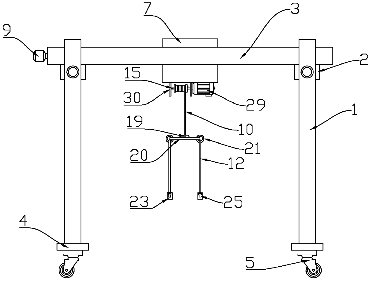
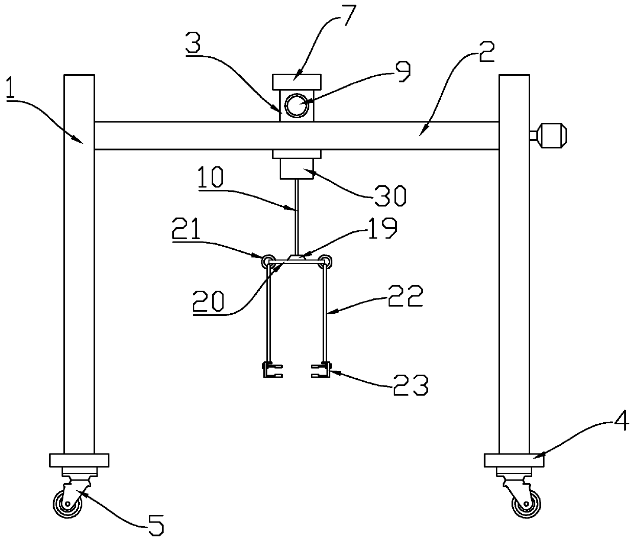
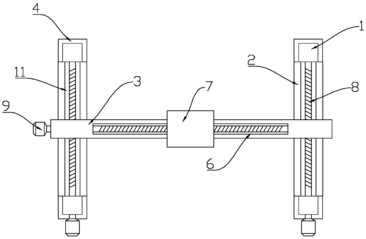
[0025] refer to Figure 1-7 , an intelligent high-efficiency hoisting device for metal composite board transportation, including a vertical bar 1 and a horizontal bar 2, the horizontal bar 2 is fixedly welded between the tops of the two vertical bars 1, and the top of the horizontal bar 2 is slidably provided with a connecting rod 3, and the cross bar 2 is located at both ends of the connecting rod 3, and a longitudinal movement mechanism is arranged between the cross bar 2 and the connecting rod 3. The limit slider 12 at the bottom, the limit slider 12 is slidably arranged in the inside of the chute 11, the limit slider 12 is provided with a driving mechanism, and the connecting rod 3 is provided with a translation slider 7 through a lateral movement mechanism, and the lateral movement The mechanism includes a through groove 6 set in the middle of the connecting rod 3, the through groove 6 runs through the upper and lower ends of the connecting rod 3, the translation slider 7...
Embodiment 2
[0027] refer to image 3 , 5 and 6, as another preferred embodiment of the present invention, the difference from Embodiment 1 is that the drive mechanism includes a threaded rod 8 that is rotatably arranged inside the through groove 6 and the chute 11, and the two ends of the threaded rod 8 are rotatably arranged through bearings In the connecting rod 3 and the cross bar 2, and one end of the threaded rod 8 extends to the outside through the connecting rod 3 and the cross bar 2, and the bolt rod 8 outside the connecting rod 3 and the cross bar 2 is fixedly connected with a servo motor 9, and the screw thread The rod 8 runs through the translation slider 7 and the limit slider 12, and the threaded rod 8 is threadedly connected with the translation slider 7 and the limit slider 12. The rotation of the threaded rod 8 can be operated by controlling the servo motor 9. When the threaded rod 8. When rotating, under the action of the screw meshing connection, the translation slider ...
Embodiment 3
[0029] refer to Figure 5 , as another preferred embodiment of the present invention, the difference from Embodiment 1 is that the translation slider 7 includes a square block 13 slidingly arranged in the through groove 6, and the upper and lower ends of the square block 13 are fixedly welded with limit sliders 14. The limit slider 14 is against the upper and lower side walls of the connecting rod 3. Under the action of the limit slider 14, the translation slider 7 can only slide in the through groove 6, and the limit slider 14 The arrangement also ensures that the translation slider 7 is always parallel to the connecting rod 3 .
PUM
 Abstract
Description
Claims
Application Information
 - R&D
- Intellectual Property
- Life Sciences
- Materials
- Tech Scout
- Unparalleled Data Quality
- Higher Quality Content
- 60% Fewer Hallucinations
Browse by: Latest US Patents, China's latest patents, Technical Efficacy Thesaurus, Application Domain, Technology Topic, Popular Technical Reports.
© 2025 PatSnap. All rights reserved.Legal|Privacy policy|Modern Slavery Act Transparency Statement|Sitemap|About US| Contact US: help@patsnap.com


