
Combination valve with oil return path compensation load-sensitive function

A load-sensitive, oil-return technology, applied in servo motor components, fluid pressure actuating devices, mechanical equipment, etc., can solve the problem of asynchronous work of multiple actuators, and achieve high work efficiency, response performance, and stable work performance. , the effect of reducing energy waste

Active Publication Date: 2020-04-17
HEFEI UNIV OF TECH
View PDF12 Cites 6 Cited by
  • Summary
  • Abstract
  • Description
  • Claims
  • Application Information

AI Technical Summary

Problems solved by technology

[0005] The technical problem to be solved by the present invention is to provide a combined valve with the load-sensing function of oil return circuit compensation, which not only has the energy-saving characteristics of the load-sensing function, but also has a simple structure, good interchangeability, and high efficiency and economic benefits , to solve the problem of asynchronous work of multiple actuators in the state of flow saturation in the load sensitive system, reduce the energy waste caused by the simultaneous throttling of the inlet and outlet ports of the proportional directional valve, and improve the energy utilization rate of the hydraulic system; through the independent control technology of the inlet and outlet The adjustment of the pressure of the oil return circuit of the sensitive system enhances the stability of the actuator operation of the system

Method used


Image

  • Combination valve with oil return path compensation load-sensitive function
  • Combination valve with oil return path compensation load-sensitive function
  • Combination valve with oil return path compensation load-sensitive function

Examples


Embodiment Construction

[0034] The preferred embodiments of the present invention will be described in detail below in conjunction with the accompanying drawings, so that the advantages and features of the present invention can be more easily understood by those skilled in the art, so as to define the protection scope of the present invention more clearly.

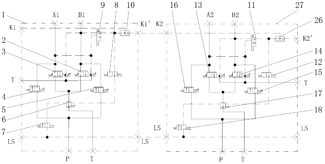
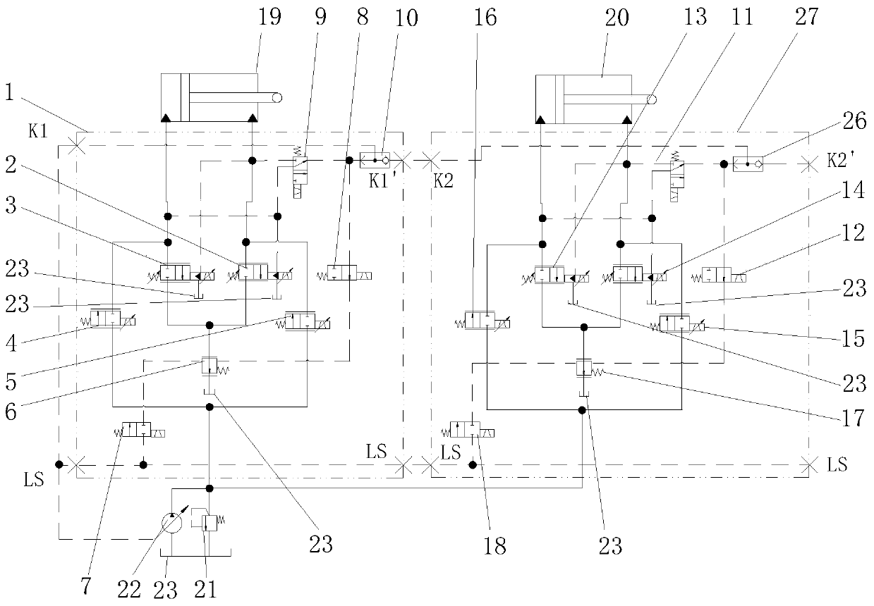
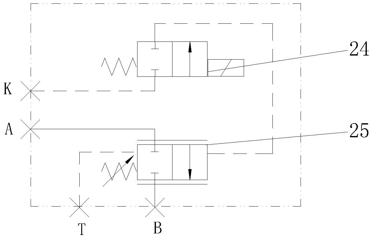
[0035] see Figure 1 to Figure 3, a combination valve with load-sensing function of oil return circuit compensation, including multi-valve group, supply oil circuit P, return oil circuit T, load-sensing oil circuit LS, multi-connected valve group shares a unified supply oil circuit P, return circuit Oil circuit T and load sensing oil circuit LS, each valve group has an output oil port An and an output oil port Bn connected with the actuator, and the multi-valve group includes the first valve group 1, the second valve group Group 27, the third valve group, ..., the Nth valve group (the third to the Nth valve group are not shown in the figure), whe...


PUM


Abstract

The invention discloses a combination valve with an oil return path compensation load-sensitive function. The combination valve comprises multiple link valve sets, an oil supply path P, an oil returnpath T and a load-sensitive oil path LS, the multiple link valve sets share the uniform oil supply path P, the oil return path T and the load-sensitive oil path LS, all the link valve sets are provided with the same components, the same device constitution and the same structure connecting relation, and the first link valve set comprises a first link first two-position two-way proportional valve,a first link second two-position two-way proportional valve, a first link first two-position two-way electric hydraulic proportional valve, a first link second two-position two-way electric hydraulicproportional valve, a first link pressure compensation valve and a first link control oil path. According to the combination valve, the system has the energy-saving feature of the load-sensitive function by adjusting the pressure of the oil return path of a load-sensitive system through the inlet-outlet independent control technology, the problem of out-of-step working of multiple executors in a flow saturation state in the load-sensitive system is solved, throttling loss when the oil return path passes through a valve port is reduced, and the running stability of the executors of the system is enhanced.

Description

technical field [0001] The invention relates to a combination valve capable of independent control of the inlet and outlet oil passages, in particular to a combination valve capable of independently controlling the inlet and outlet oil passages and having the oil return circuit compensation load sensitive function. Background technique [0002] Hydraulic transmission and control technology is one of the key technologies of transmission and control in the era of Industry 4.0. All countries in the world have paid great attention to hydraulic transmission and control technology. The hydraulic system is characterized by high power density, compact structure, good controllability and strong environmental adaptability, but the disadvantages are high installed power and low energy utilization rate. Empty, the working speed of the actuator is greatly affected by the change of the load, and the work of multiple actuators is not synchronized under the state of flow saturation. [000...

Claims


Application Information

Patent Timeline
Patent Type & Authority Applications(China)
IPC IPC(8): F15B13/02
CPCF15B13/021
Inventor 曾亿山黄河刘旺刘常海刘睿
Owner HEFEI UNIV OF TECH
Learn More