Hydraulic pressure control device for machinery

A technology for working machinery and control devices, which is applied to fluid pressure actuation devices, mechanical equipment, mechanically driven excavators/dredgers, etc., can solve problems such as energy loss, reduce overflow flow, etc. The effect of improving energy efficiency and improving operational performance

Active Publication Date: 2015-06-24
NIHON KENKI CO LTD
View PDF7 Cites 12 Cited by
  • Summary
  • Abstract
  • Description
  • Claims
  • Application Information

AI Technical Summary

Problems solved by technology

However, in this case, the overflow flow returned from the relief valve to the tank also becomes an energy loss, and technical development to reduce the overflow flow is required

Method used


Image

  • Hydraulic pressure control device for machinery
  • Hydraulic pressure control device for machinery
  • Hydraulic pressure control device for machinery

Examples


no. 1 Embodiment approach

[0054] ~The first embodiment~

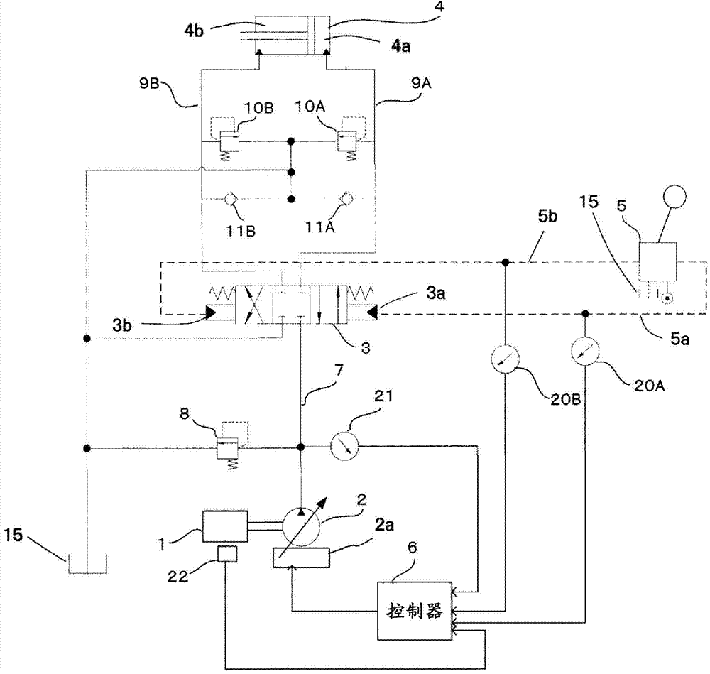
[0055] figure 2 It is a figure which shows a part of the hydraulic pressure control apparatus in 1st Embodiment of this invention.

[0056] The hydraulic control device of the present embodiment has: a prime mover (such as a diesel engine) 1; a variable displacement hydraulic pump 2 driven by the prime mover 1; driven by oil; directional control valve 3, which controls the flow of hydraulic oil supplied from hydraulic pump 2 to hydraulic actuator 4; operating lever device 5, which is used for the operator to input operation instructions; main relief valve 8, which is connected with the hydraulic pressure The pump discharge oil passage 7 connected to the pump 2 and the directional control valve 3 is connected, and the upper limit of the pressure of the pump discharge oil passage 7 (discharge pressure of the hydraulic pump 2) is specified; And the main relief valve 8 and other connections.

[0057] The hydraulic pump 2 is, for example, a varia...

no. 2 Embodiment approach

[0083] ~Second Embodiment~

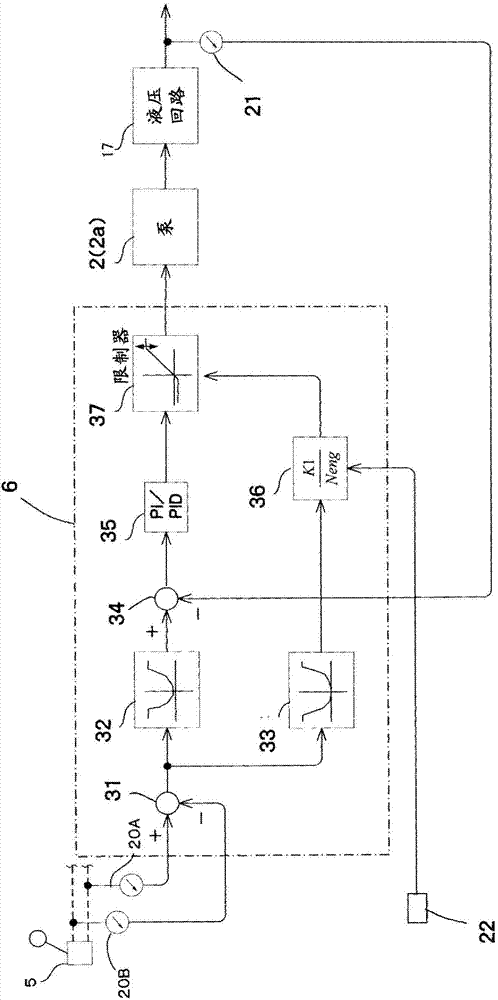
[0084] Figure 6 It is a figure which shows the control logic of the controller of the hydraulic pressure control apparatus in 2nd Embodiment of this invention. In the figure, the same reference numerals are attached to the same elements as those of the first embodiment, and description thereof will be omitted.

[0085] Figure 6 In this embodiment, the controller 6A is image 3 In addition to the shown configuration, the pump power upper limit setting device 41 sets a power limit value Pwr_ref for limiting the amount of absorbed power of the hydraulic pump 2; a flow rate correction unit 42 (flow rate limit value correction unit) , which is obtained by dividing the power limit value Pwr_ref set by the pump power upper limit setting device 41 by the discharge pressure (current pressure) of the hydraulic pump 2 detected by the pressure detector 21 and multiplying it by the correction coefficient K2, and Calculate the pump flow upper limit value; ...

no. 3 Embodiment approach

[0097] ~Third Embodiment~

[0098] Figure 10 It is a figure which shows the structure of the pump control apparatus of the hydraulic pressure control apparatus in 3rd Embodiment of this invention, and the control logic of a controller. In the figure, the same reference numerals are attached to the same elements as those of the first embodiment, and description thereof will be omitted.

[0099] In the first embodiment, the controller 6 has all the functions up to the determination of the target tilting amount of the hydraulic pump 2 and these functions are executed by software, so that the mechanical regulator 2 a has the function determined by the controller 6 . However, in this embodiment, the controller 6B has the functions of the target pump pressure setting unit 32 and the pump flow rate upper limit setting unit 33, and the mechanical regulator 2aA has the functions of the other functions. Processing function (feedback subtraction unit 34, control amount calculation uni...


PUM


Abstract

The present invention improves energy efficiency by reducing the throttling-off loss of the delivery flow rate of a hydraulic pump due to bleed-off control and improves operational performance by enabling control of hydraulic pump delivery pressure according to the control input of an operating lever device. A controller (6) comprises a target pump pressure-setting unit (32) for calculating, on the basis of control input signals from control input detectors (20A, 20B), a target pump delivery pressure, which increases as the control input signals increase, and a pump flow rate upper limit-setting unit (33) for calculating, on the basis of the control input signals, the pump flow rate upper limit, which increases as the control input signals increase. The amount of tilt of the hydraulic pump (2) is controlled on the basis of the target pump delivery pressure calculated by the target pump pressure-setting unit (32), the pump flow rate upper limit calculated by the pump flow rate upper limit-setting unit (33), and the delivery pressure of the hydraulic pump (2) detected by a pressure detector (21).

Description

technical field [0001] The invention relates to a hydraulic control device for working machines such as hydraulic excavators. Background technique [0002] Conventionally, as a hydraulic control device for an operating machine, a hydraulic system of the following bleed-off method has been commonly used: a bleed-off passage is provided on a directional control valve, and the bleed-off passage is arranged on a bypass line. The directional control valve controls the flow of hydraulic oil discharged from the hydraulic pump and supplied to the hydraulic actuator. The hydraulic system of the bleed type controls the flow rate to the actuator by performing bleed control such that a part of the discharge flow rate of the hydraulic pump is returned to the tank through the bleed passage according to the operation amount (stroke) of the directional control valve. [0003] For hydraulic systems of such a relief type, from the viewpoint of improving energy efficiency, technical developme...

Claims


Application Information

Patent Timeline
Patent Type & Authority Applications(China)
IPC IPC(8): F15B11/00E02F9/22F15B11/02
CPCE02F3/32E02F9/2235E02F9/2285E02F9/2296F15B11/0423F15B2211/6654F15B2211/6652F15B2211/6316F15B2211/6309F15B2211/3111F15B2211/20546F15B2211/633F15B2211/6653F15B2211/6346E02F9/22F15B11/028F15B2211/251F15B2211/30525F15B2211/365F15B2211/6333
Inventor 宇田川勉中山晃山下亮平泉枝穗枝村学石川广二佐竹英敏
Owner NIHON KENKI CO LTD
Why Eureka
Try Eureka