Center rotating joint provided with angle sensor

A central rotary joint and angle sensor technology, applied in the direction of pipes/pipe joints/pipe fittings, mechanical equipment, pipe components, etc., can solve the problems of not being able to truly reflect the rotation angle, poor reliability, and reduced flow area, and achieve processing and production Low cost, easy maintenance or replacement, stable and reliable work

Active Publication Date: 2020-04-17
JIANGSU CHANGLING HYDRAULIC CO LTD
View PDF6 Cites 0 Cited by
  • Summary
  • Abstract
  • Description
  • Claims
  • Application Information

AI Technical Summary

Problems solved by technology

[0006] In the installation method of the above-mentioned rotary center joint, the middle slender shaft needs to have better structural strength due to the longer shaft, and also requires higher machining accuracy. The cover plate is fixed, and there is oil in the channel of the slender shaft, so the slender shaft is suspended in the middle oil channel, so there may be deflection during the rotation process, and the rotation angle cannot be truly reflected
In addition, since the slender shaft occupies the oil passage space of the middle oil passage, the flow area will be reduced, the back pressure of the oil passage will increase, and the oil drainage of the traveling motor will be poor.
[0007] Existing angle sensors installed on the central rotary joint have different degrees of complex structures, poor reliability, low measurement accuracy, and inconvenient maintenance.

Method used


Image

  • Center rotating joint provided with angle sensor
  • Center rotating joint provided with angle sensor
  • Center rotating joint provided with angle sensor

Examples


Embodiment Construction

[0029] The specific implementation manners of the present invention will be further described below in conjunction with the drawings and examples. The following examples are only used to illustrate the technical solution of the present invention more clearly, but not to limit the protection scope of the present invention.

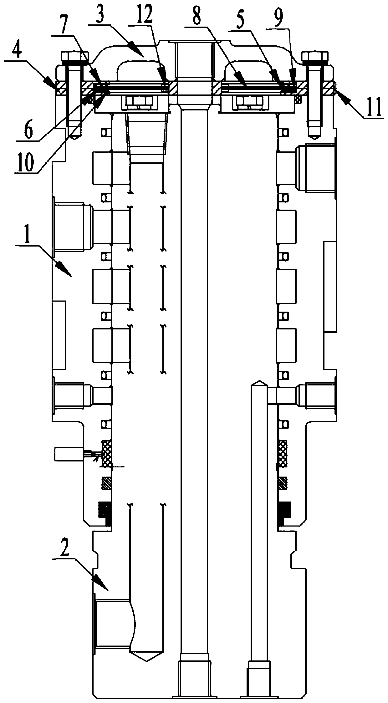
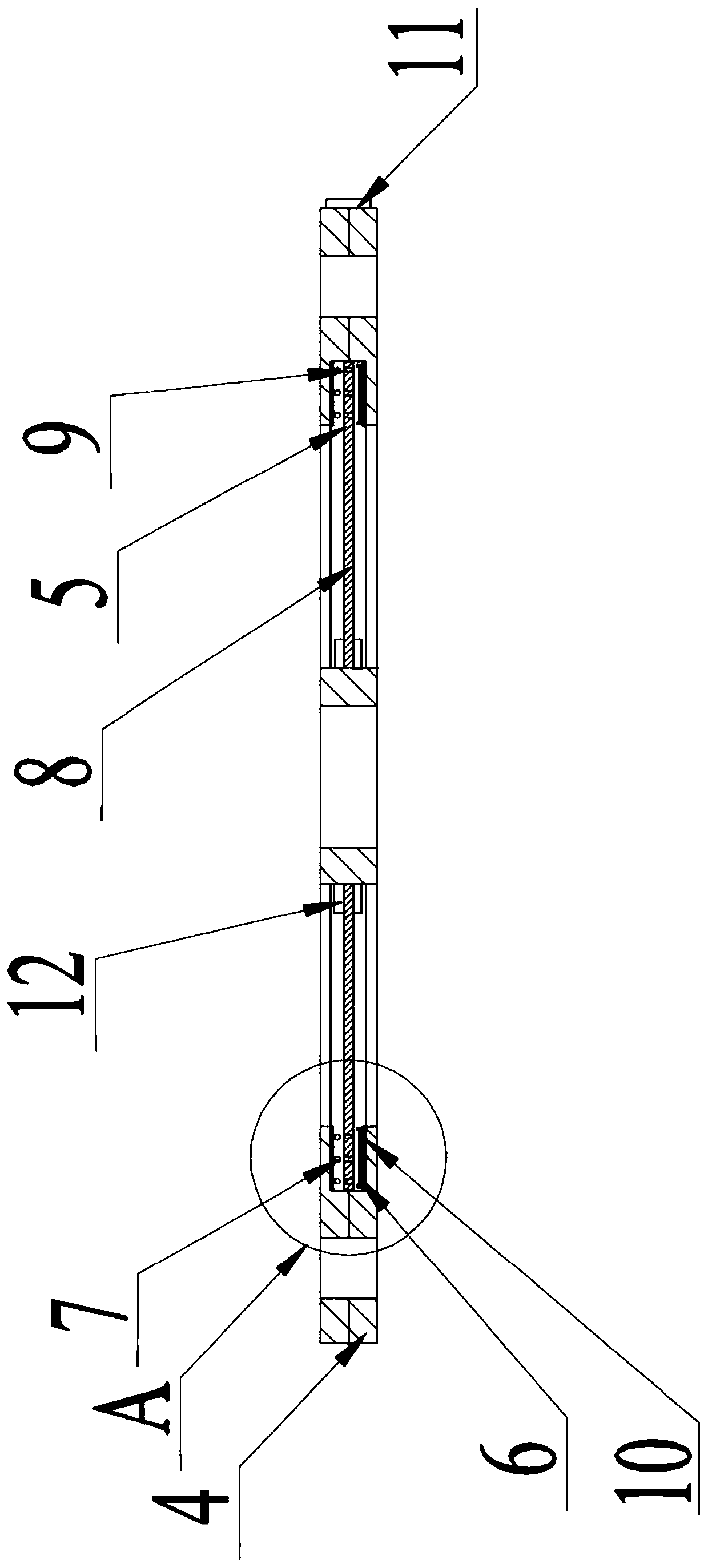
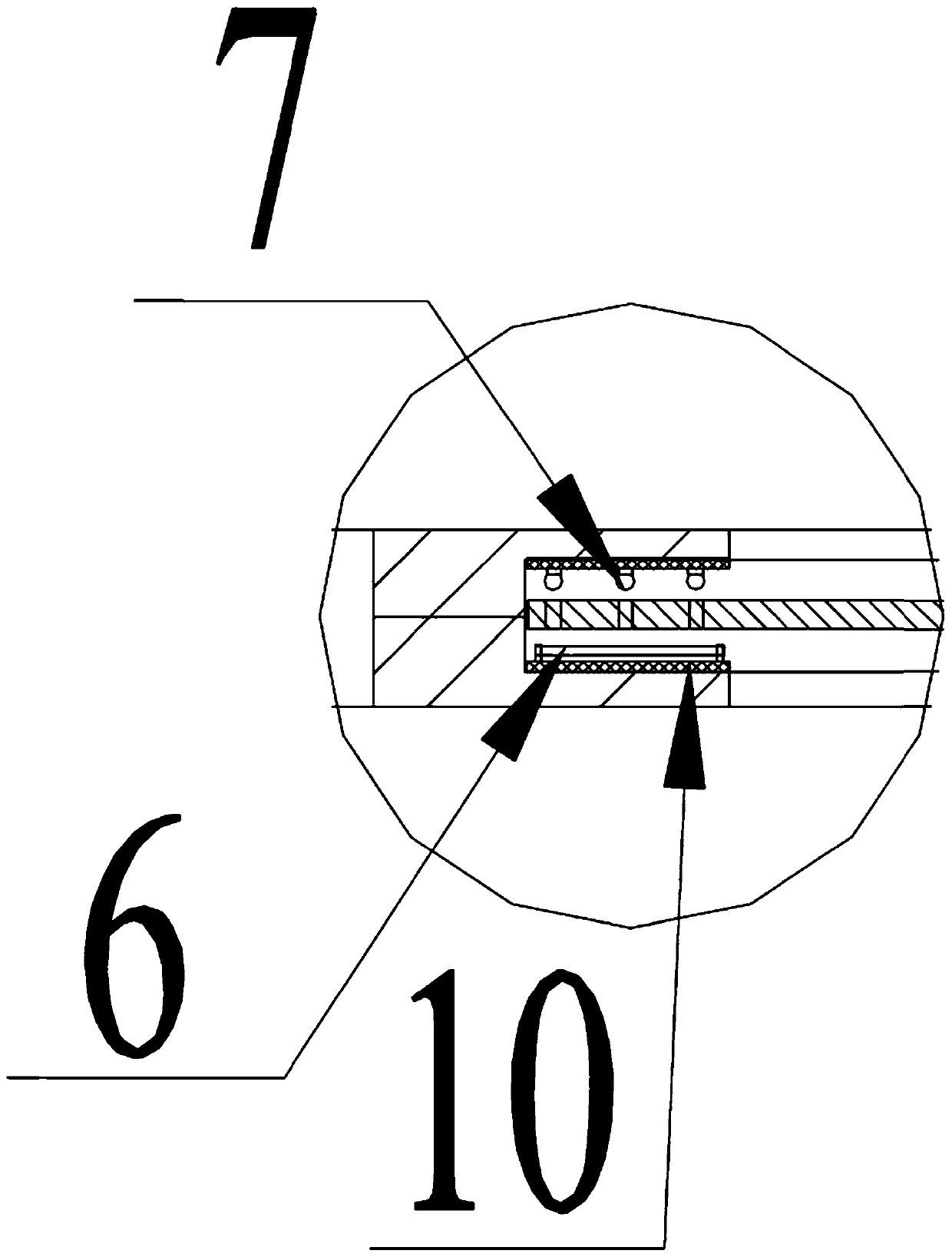
[0030] Such as Figure 1-7 As shown, the present invention is a central rotary joint provided with an angle sensor. The central rotary joint includes a rotary body 1, a rotary shaft 2 and an end cover 3, and an angle sensor is provided at the connection between the rotary body 1 and the end cover 3. The installation ring 4 is provided with an annular groove 5 on the inner ring of the angle sensor installation ring 4, and an angle signal transmitting device 5 and an angle signal receiving device 7 are respectively provided on the two opposite ring surfaces in the annular groove 5, and an angle signal transmitting device 7 is arranged on the angle signal tran...


PUM


Abstract

The invention discloses a center rotating joint provided with an angle sensor. The center rotating joint comprises a rotating body, a rotating shaft and an end cover. An angle sensor mounting ring isarranged at the connecting portion of the rotating body and the end cover. An annular groove is formed in an inner ring of the angle sensor mounting ring. An angle signal transmitting device and an angle signal receiving device are correspondingly arranged on two opposite annular faces in the annular groove. A rotating disc connected with the rotating shaft is arranged between the angle signal transmitting device and the angle signal receiving device. A through hole or an opening groove corresponding to the angle signal transmitting device and the angle signal receiving device in position is formed in the rotating disc. The angle signal transmitting device and the angle signal receiving device are connected with a controller. The center rotating joint provided with the angle sensor has thebeneficial effects of being simple in structure, convenient and fast to use, stable and reliable in work, convenient to maintain, low in machining and manufacturing cost and the like.

Description

technical field [0001] The invention relates to the technical field of hydraulic rotary joints, in particular to a central rotary joint provided with an angle sensor. Background technique [0002] The excavator includes an upper platform and a lower frame, and the upper platform is slewably mounted on the lower frame. The power system of the excavator and the oil tank, pump and control valve in the hydraulic system are installed on the upper platform. Hydraulic actuators such as a hydraulic motor for traveling and a bulldozing blade lifting cylinder are installed on the lower frame. Due to the relative rotation of the upper platform and the lower frame, the hydraulic actuators installed on the lower frame need to be connected with the hydraulic components on the upper platform through the rotary center joint. [0003] The existing slewing center joint includes a central joint body and a mandrel. The central joint body is sleeved on the lower part of the mandrel. When insta...

Claims


Application Information

Patent Timeline
Patent Type & Authority Applications(China)
IPC IPC(8): F16L39/06F16L55/00
CPCF16L39/06F16L55/00
Inventor 夏泽民张爱军潘逸明陶科缪勤竹
Owner JIANGSU CHANGLING HYDRAULIC CO LTD
Why Eureka
Try Eureka