A kind of engineering measuring device and using method
A technology of engineering measurement and adjustment devices, which is applied in the direction of measuring devices, instruments, pipe components, etc., can solve problems such as the influence of adjacent pipelines and the influence of underground pipeline detection work, and achieve the effect of ensuring accuracy
- Summary
- Abstract
- Description
- Claims
- Application Information
AI Technical Summary
Problems solved by technology
Method used
Image
Examples
Embodiment 1
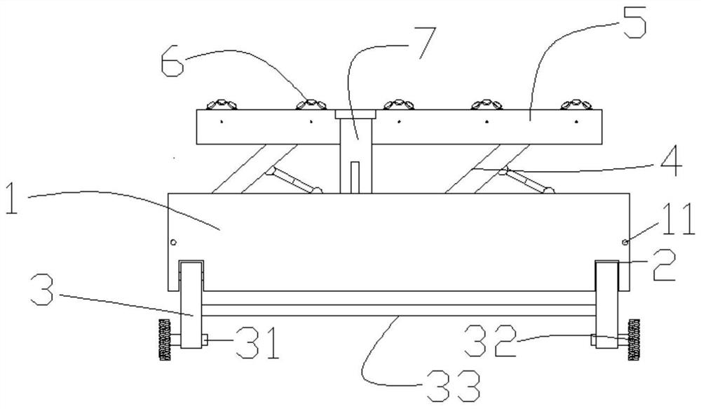
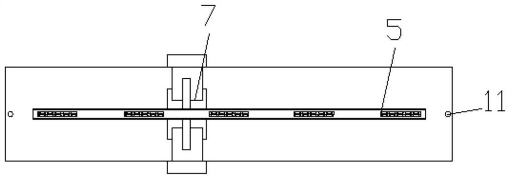
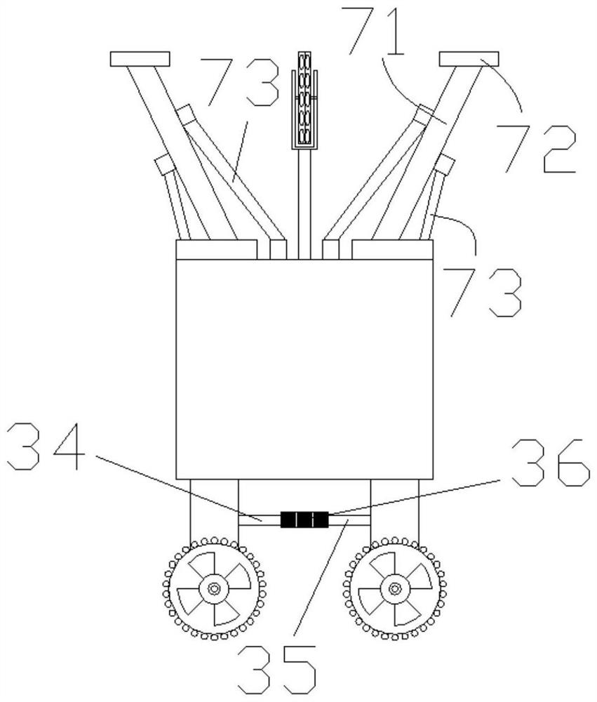
[0061] see Figure 1-3 , an engineering measuring device, the device includes a main body 1, a driving module and a driven module. in,
[0062] Several concave installation spaces 2 are formed at the bottom of the main body 1 .
[0063] Preferably, there are four installation spaces 2 , and the four installation spaces 2 are respectively located at the bottom of the main body 1 near the four corners.
[0064] The active module includes a foot 3 , a motor 31 , a mecanum wheel 32 and a connecting rod 33 . in,
[0065] The number of the legs 3 is equal to that of the installation space 2, and the two are in a one-to-one relationship. Each installation space 2 is hinged with a leg 3 through a rotating shaft, so that each leg 3 can protrude from the side of the main body 1 around the rotating shaft and take back. A motor 31 is fixedly arranged at the end of each leg 3 , and the motor 31 is arranged along the length direction of the main body 1 , and a mecanum wheel 32 is conne...
Embodiment 2
[0075] On the basis of Embodiment 1, this embodiment further proposes a technical solution to realize the span adjustment of the legs, thereby ensuring that the main body 1 is located at the axis of the pipeline. details as follows.
[0076] see Figure 1-3 , the legs 3 located on the same side of the main body 1 and distributed along the length direction of the main body 1 are connected by connecting rods 33 .
[0077] The legs 3 located on one end of the main body 1 and symmetrically distributed on both sides of the main body 1 are connected through a first cross bar 34 , a second cross bar 35 and an adjustment device 36 .
[0078] The legs 3 located on the other end of the main body 1 and symmetrically distributed on both sides of the main body 1 are connected through the first cross bar 34 , the second cross bar 35 and the buffer module.
[0079] see Figure 5 , the adjusting device 36 includes: a rotating cylinder 361 , a pressing piece 362 and a locking device arrange...
Embodiment 1-2
[0093] Based on embodiment 1-2, the using method of described a kind of measuring device is specifically as follows:
[0094] S1. Place the measuring device in the pipeline, pull away all the measuring rulers 11, push the ends of all the measuring rulers 11 to the pipe wall, and measure whether the centerline of the main body 1 coincides with the centerline of the pipeline; if the two coincide, then Skip to step S5; if the two do not overlap, then jump to step S2;
[0095] S2. The user holds the pressing piece 362 and the rotary cylinder 361 to lower the pressing piece 362, so that the connecting spring 363 is compressed, and the pressing spring 365 is also compressed, driving the inner end of the lever 364 to press down, so that the outer end of the lever 364 rises , to drive the locking teeth 367 to rise, and break away from the clamping position on the external thread of the first cross bar 34 and / or the second cross bar 35;
[0096] S3. The user rotates the rotary drum 36...
PUM
 Abstract
Description
Claims
Application Information
 - R&D
- Intellectual Property
- Life Sciences
- Materials
- Tech Scout
- Unparalleled Data Quality
- Higher Quality Content
- 60% Fewer Hallucinations
Browse by: Latest US Patents, China's latest patents, Technical Efficacy Thesaurus, Application Domain, Technology Topic, Popular Technical Reports.
© 2025 PatSnap. All rights reserved.Legal|Privacy policy|Modern Slavery Act Transparency Statement|Sitemap|About US| Contact US: help@patsnap.com


