LED collimating optical lens

A collimating optics and lens technology, applied in the field of LED secondary optics design, can solve problems such as glare, uneven illumination, and poor uniformity of illumination spots

Active Publication Date: 2020-04-17
SOUTHEAST UNIV
View PDF4 Cites 3 Cited by
  • Summary
  • Abstract
  • Description
  • Claims
  • Application Information

AI Technical Summary

Problems solved by technology

[0004] At present, there are many kinds of LED collimating lenses based on free-form surface design, but there are generally problems such as poor uniformity of illumin...

Method used


Image

  • LED collimating optical lens
  • LED collimating optical lens
  • LED collimating optical lens

Examples


Embodiment

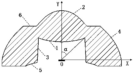
[0069] An LED collimating optical lens according to the present invention can be divided into a refraction part and a reflection part according to the collimation method. The refraction part includes a first free-form surface 1 and a second free-form surface 2. The first part of the refraction part A free-form surface 1 and the second free-form surface 2 shapes are determined by the following method:

[0070] First divide the boundary angle α equally, and then establish the light emission angle θ according to the law of energy conservation i (θ i ≤α) and reach the target area radius r after passing through the lens i Then use Snell's law to establish the iterative relationship of the coordinates of two adjacent points on the free curve, and finally obtain the discrete coordinates of each point on the contour line of the free surface by giving the initial parameters and the iterative relationship.

[0071] There are two free-form surfaces in the refraction part, and the speci...


PUM


Abstract

The invention discloses an LED collimating optical lens. The LED collimating optical lens comprises a refraction part and a reflection part, wherein the refraction part comprises a first free-form surface and a second free-form surface which form an incident surface and an emergent surface of the refraction part correspondingly; the reflection part comprises a circular truncated cone surface, a third free-form surface, a fourth free-form surface and a ring surface; the circular truncated cone surface is the incident surface of the reflection part; the ring surface is the emergent surface of the reflection part; and the circular truncated cone surface and the first free-form surface form a cavity area in the center of the bottom of the lens. The problems of non-uniform energy distribution,glare and the like commonly existing in the prior art are solved, and the novel LED collimating optical lens is provided and is simple in structure, good in collimating effect, high in optical efficiency and free of glare.

Description

technical field [0001] The invention belongs to the field of LED secondary optical design, and in particular relates to an LED collimating optical lens. Background technique [0002] With the development of semiconductor light-emitting diode technology and the country's promotion of green lighting, LED light sources have become increasingly prominent in the field of lighting; LED, as a new type of energy-saving light source, has a compact structure compared with traditional light sources such as mercury lamps and halogen lamps. , low price, energy saving and environmental protection, long service life, good color balance and other outstanding advantages, and when used as a projection light source, there is no need to extract basic colors from white light, because the spectrum of LEDs can be artificially controlled. At present, as a new type of light source, LED has been widely used in many fields such as general lighting, landscape lighting, display screen, backlight applica...

Claims


Application Information

Patent Timeline
IPC IPC(8): F21V5/04F21Y115/10
CPCF21V5/046F21Y2115/10
Inventor 陈云飞汪洋张艳
Owner SOUTHEAST UNIV
Why Eureka
Try Eureka