Rotating type drying device for sheet-like food
A drying device and rotary technology, applied in the direction of drying gas arrangement, non-progressive dryer, drying solid materials, etc., can solve the problems of uneven drying, large loss, etc., to speed up drying, improve work efficiency, and speed up Bleeding effect
- Summary
- Abstract
- Description
- Claims
- Application Information
AI Technical Summary
Problems solved by technology
Method used
Image
Examples
Embodiment 1
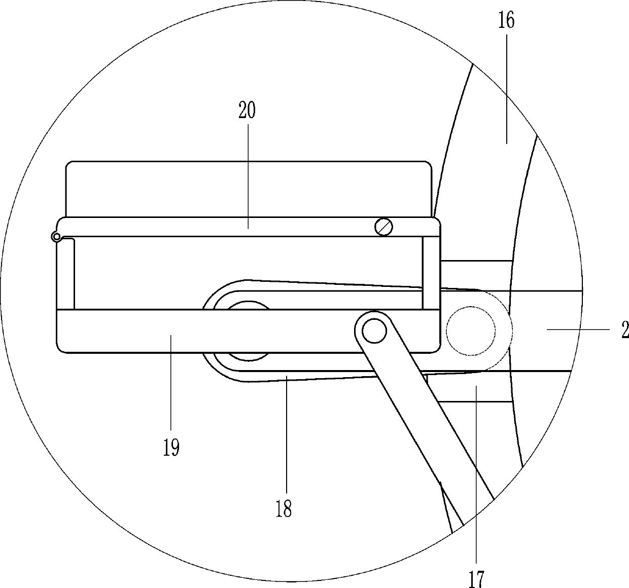
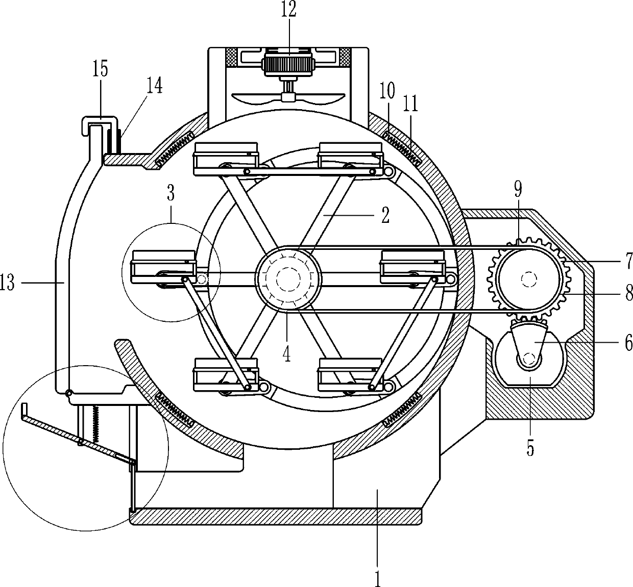
[0017] A rotary drying device for flake food, such as figure 1 and 2 As shown, it includes an installation box 1, a rotating rod 2, a power assembly, a food placement assembly 3, a heating wire 11, a fan 12, a cover plate 13, a hollow tube 14 and a clamping rod 15. The middle of the installation box 1 is equipped with a rotary Rod 2, the rotating rod 2 is provided with six food placing components 3, the right side of the installation box 1 is installed with a power component that drives the rotation rod 2 to rotate by means of transmission, the inside of the installation box 1 is provided with four grooves 10, the grooves 10 A heating wire 11 is installed on the installation box 1 inside, a fan 12 is installed on the top of the installation box 1, a cover plate 13 is rotatably provided on the lower part of the left side of the installation box 1, and a hollow tube 14 is arranged on the installation box 1 on the right side of the cover plate 13. , the hollow tube 14 is slidabl...
Embodiment 2
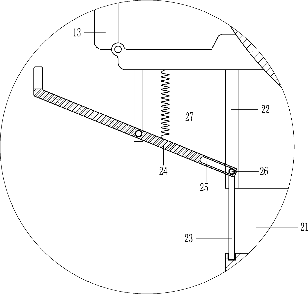
[0024] like figure 1 and 3 As shown, on the basis of Embodiment 1, in order to prevent people from getting burned when taking out the food, the guide rail 22, the baffle plate 23, the pull rod 24, the circular shaft 26 and the spring 27 are also included, and the bottom of the installation box 1 is provided with a through hole 21, The lower part of the left side of the installation box 1 is fixed with a guide rail 22 by bolts, a baffle plate 23 is slidably arranged on the guide rail 22, a pull rod 24 is rotatably provided on the top left side of the installation box 1 of the guide rail 22, and a sliding groove is opened on the right part of the pull rod 24 25. A circular shaft 26 is slidably arranged in the sliding groove 25, the rear side of the circular shaft 26 is connected with the baffle plate 23, and a spring 27 is welded between the top right side of the pull rod 24 and the installation box 1.
[0025] In the specific implementation of the above embodiment, after the f...
PUM
 Abstract
Description
Claims
Application Information
 - R&D
- Intellectual Property
- Life Sciences
- Materials
- Tech Scout
- Unparalleled Data Quality
- Higher Quality Content
- 60% Fewer Hallucinations
Browse by: Latest US Patents, China's latest patents, Technical Efficacy Thesaurus, Application Domain, Technology Topic, Popular Technical Reports.
© 2025 PatSnap. All rights reserved.Legal|Privacy policy|Modern Slavery Act Transparency Statement|Sitemap|About US| Contact US: help@patsnap.com


