Carrier rocket tail sub-stage structure

A technology of launch vehicles and rockets, applied in the field of aerospace, can solve the problems of unreasonable layout, weak carrying capacity, complex assembly, etc., and achieve the effect of improving carrying efficiency, strong carrying capacity, and reducing self-weight

Pending Publication Date: 2020-04-17
BEIJING XINGJI RONGYAO SPACE TECH CO LTD +1
View PDF0 Cites 7 Cited by
  • Summary
  • Abstract
  • Description
  • Claims
  • Application Information

AI Technical Summary

Problems solved by technology

[0005] Therefore, the technical problem to be solved by the present invention is to overcome the technical problems of unreasonable layout, complex assembly, high requirements, weak bearing capacity and heavy weight of the launch vehicle terminal structure in the prior art, thereby providing a launch vehicle terminal level structure

Method used


Image

  • Carrier rocket tail sub-stage structure
  • Carrier rocket tail sub-stage structure
  • Carrier rocket tail sub-stage structure

Examples


Embodiment Construction

[0041] The technical solutions of the present invention will be clearly and completely described below in conjunction with the accompanying drawings. Apparently, the described embodiments are some of the embodiments of the present invention, but not all of them. Based on the embodiments of the present invention, all other embodiments obtained by persons of ordinary skill in the art without making creative efforts belong to the protection scope of the present invention.

[0042] In the description of the present invention, it should be noted that the terms "center", "upper", "lower", "left", "right", "vertical", "horizontal", "inner", "outer" etc. The indicated orientation or positional relationship is based on the orientation or positional relationship shown in the drawings, and is only for the convenience of describing the present invention and simplifying the description, rather than indicating or implying that the referred device or element must have a specific orientation, ...


PUM


Abstract

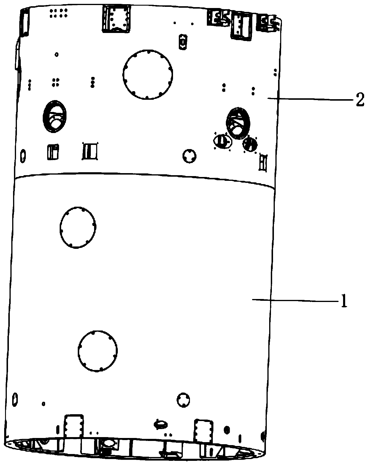
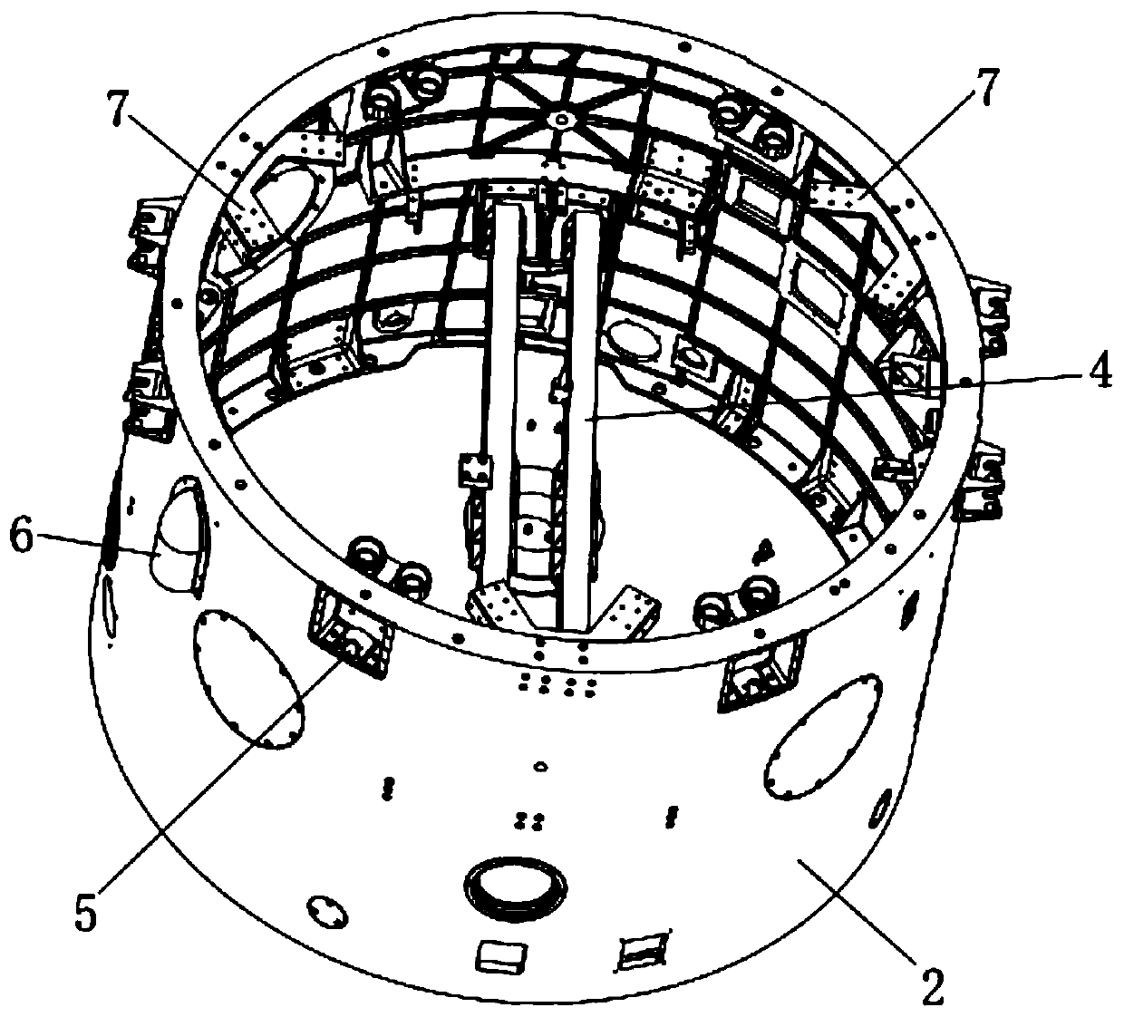
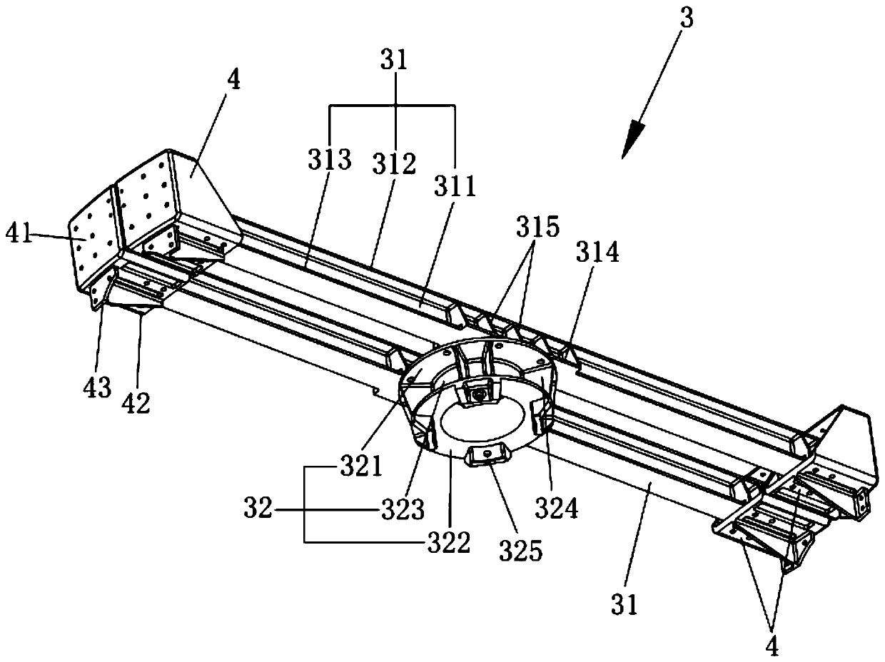
The invention discloses a carrier rocket tail sub-stage structure, which comprises a power cabin, an instrument cabin and a stiffening beam structure, wherein the power cabin provides mounting space for a tail sub-stage power system; the instrument cabin is connected to the upper end of the power cabin, and a plurality of mounting interfaces for mounting instruments are formed in the inner wall ofthe instrument cabin; the stiffening beam structure comprises at least two stiffening beams which are arranged in parallel, and two ends of each stiffening beam are respectively connected with the inner wall of the instrument cabin; and the middle parts of the at least two stiffening beams are connected with a connecting disc for providing a connecting interface for the tail sub-stage power system. The stiffening beam structure of a double-beam parallel structure is adopted in the instrument cabin, the self weight of the stiffening beam structure can be reduced on the premise that the stability of a connecting disc installation structure is guaranteed, the power cabin and the instrument cabin are respectively made of an integrated structure, and the effect of reducing the self-weight of the whole carrier rocket tail sub-stage structure can also be achieved. Meanwhile, the inner wall of the instrument cabin can provide mounting interfaces for a large quantity of equipment, and the carrying efficiency of the rocket is improved while the starting resistance during rocket launching is reduced.

Description

technical field [0001] The invention relates to the field of aerospace technology, in particular to a final stage structure of a carrier rocket. Background technique [0002] The launch vehicle is usually used as a means of transportation to send payloads such as various satellites into space. The launch vehicle is usually composed of two to four stages, and each stage includes a rocket body structure and an engine. [0003] The last stage of the launch vehicle is generally equipped with electrical equipment for the entire rocket, including guidance and control systems, telemetry systems, safety systems, etc., and there are many instrument installation interfaces. It is also necessary to install the power system of the last sub-stage, which must bear a relatively large load. In addition, satellites are usually installed on the last sub-level, which requires the last sub-level to provide a reliable installation interface. [0004] The last stage of the launch vehicle enters...

Claims


Application Information

Patent Timeline
Patent Type & Authority Applications(China)
IPC IPC(8): F42B15/00
CPCF42B15/00
Inventor 彭小波郑立伟崔深山
Owner BEIJING XINGJI RONGYAO SPACE TECH CO LTD
Why Eureka
Try Eureka