
Aero-engine test bed mounting system

An aero-engine and installation system technology, which is applied in engine testing, jet engine testing, gas turbine engine testing, etc., can solve the problems of inaccurate testing, low testing efficiency, and high cost, and achieve accurate testing data and disassembly and assembly efficiency. High, high-precision installation effect

Active Publication Date: 2020-04-17
湖南汉能科技有限公司
View PDF16 Cites 5 Cited by
  • Summary
  • Abstract
  • Description
  • Claims
  • Application Information

AI Technical Summary

Problems solved by technology

[0004] Aiming at the problems existing in the prior art that the working state of the aero-engine cannot be accurately simulated and the installation and use of the test pieces are inconvenient, the present invention provides an installation system for the aero-engine test bench, which solves the problem of inaccurate testing and low test efficiency in the existing test bench. high cost problem

Method used


Image

  • Aero-engine test bed mounting system
  • Aero-engine test bed mounting system
  • Aero-engine test bed mounting system

Examples


Embodiment 1

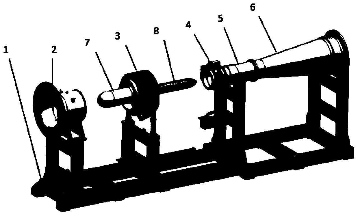
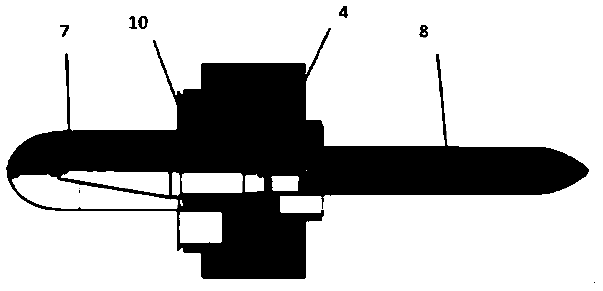
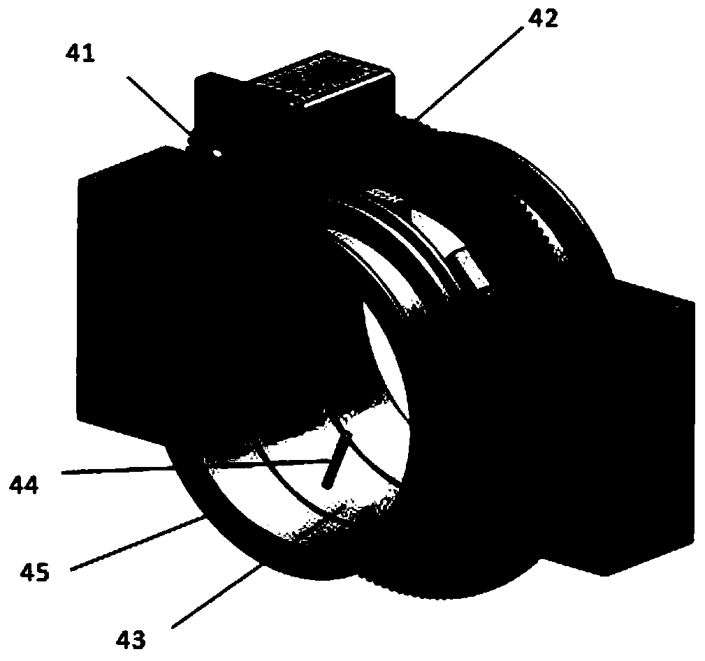
[0029] An aeroengine test bench installation system. Such as figure 1 , including a test bench 1, an air intake fairing 2 installed on the test bench 1, a test piece installation mechanism 3, a rotating measuring mechanism 4, an exhaust pipe; the exhaust pipe includes an exhaust straight pipe 5 and an expansion pipe 6. An intake cone 7 is provided in the air intake fairing, and an exhaust cone 8 is provided in the exhaust pipe. The intake shroud 2, the test piece mounting mechanism 3, the rotating measuring mechanism 4, the exhaust straight pipe 5 and the expansion section 6 are sequentially connected to form a circular tubular shape, and the intake cone assembly 7 and the exhaust cone assembly 8 are arranged in the pipe.

[0030] Such as Image 6 , 7 As shown, the test bench includes a base 11, an air intake shroud moving support 12, a test piece moving support 13, an exhaust straight pipe section mounting seat 14, and an expansion section mounting seat 15, etc. The insta...


PUM


Abstract

An aero-engine test bed mounting system comprises a test bed frame, an air inlet fairing mounted on the test bed frame, a test piece mounting mechanism, a rotary measuring mechanism and an exhaust pipe. The exhaust pipe comprises an exhaust straight pipe and an expansion pipe, an air inlet cone is arranged in the air inlet fairing, and an exhaust cone is arranged in the exhaust pipe; an air pressure measuring device is arranged in the air inlet fairing, and a plurality of air pressure measuring devices are arranged in the rotary measuring mechanism; a movable connecting unit and an air inlet fairing are arranged on the mounting rack; and the test piece mounting mechanism moves through the movable connecting unit. The installation system has the advantages of real simulation environment andaccurate measurement data.

Description

technical field [0001] The invention relates to an aeroengine test device, in particular to a test bench installation system capable of testing the aerodynamic performance of the aeroengine particle separator and the flow rate caused by anti-icing. Background technique [0002] The working conditions of the aero-engine are very harsh, in the working state of high temperature, high pressure and high-speed rotation. In order to improve the performance, reliability and life of the aero-engine, it is necessary to fully grasp the temperature, pressure, corrosion, and clearance of the aero-engine under different working conditions. and stress etc. In order to master the above data, it is usually necessary to test the aero-engine on the test bench, including component and system tests, complete machine test, etc. [0003] The particle separator is an important part installed at the inlet of an aeroengine to prevent damage to engine components, increase in fuel consumption and decr...

Claims


Application Information

Patent Timeline
Patent Type & Authority Applications(China)
IPC IPC(8): G01M15/14G01M15/02
CPCG01M15/02G01M15/14
Inventor 廖利华郭斌
Owner 湖南汉能科技有限公司
Learn More