
Eureka
For R&D, Eureka makes reading and utilizing patents & technical documents easy.
Eureka AIR
Designed for self-driven R&D workflows. Generate viable solutions, solve complex R&D challenges, empower your innovation with AI.

Eureka Materials
Designed for material experts only. Revolutionize your material R&D, from search, analyze, to developing new materials.

TechResearch
Generate reliable direction feasibility study reports for your R&D in just a few steps.

TechSeek
Discover and master advanced knowledge NOW. Basics, ideas, possibilities, all at once.

TechMind
As an expert in R&D Theories, TechMind can generates customized viable solutions instantly.

TechRisk
Analyze your overall solution with one click, know your potential R&D risks in advance.

TechMonitor
Get weekly tech updates, stay abreast of the latest tech innovations and key insights.
Liquid optical phase modulation device based on dielectrophoresis effect and use method thereof
A dielectrophoresis and liquid technology, applied in the field of liquid optical phase modulation devices, can solve the problems of low precision, complex structure of optical phase modulation devices, high cost, etc., and achieve easy production, simple adjustment measurement and calculation process, and low cost Effect
- Summary
- Abstract
- Description
- Claims
- Application Information
AI Technical Summary
Problems solved by technology
Method used
Image

Examples
Embodiment 1
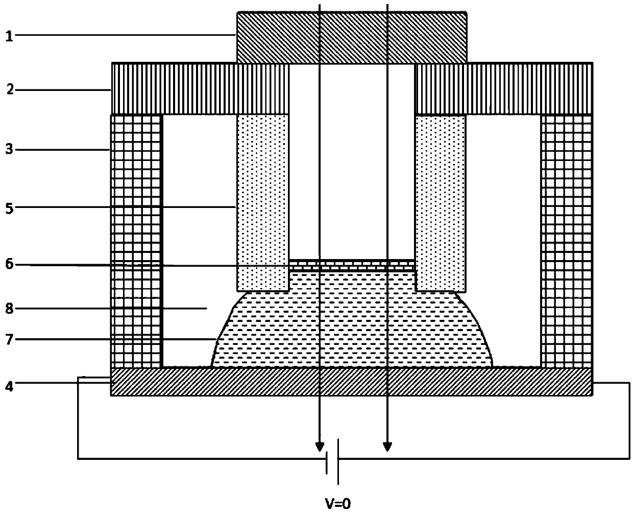
[0036] A liquid optical phase modulation device based on the dielectrophoretic effect, comprising an inner cylindrical tube 5 and an outer cylindrical tube 3 arranged inside and outside, the bottom of the outer cylindrical tube 3 is connected to the bottom electrode 4, and the inner cylindrical tube 5 There is a gap between the bottom and the bottom electrode 4, and the tops of the inner cylindrical tube 5 and the outer cylindrical tube 3 are connected by the second upper cover sheet 2, and the top of the second upper cover sheet 2 is provided with a first upper cover Sheet 1, the middle of the bottom electrode 4 is provided with a first liquid 7, the top of the first liquid 7 meets the bottom surface of the inner cylindrical tube 5, and extends upward into the inner ring of the inner cylindrical tube 5, so The closed space formed between the bottom electrode 4, the outer cylindrical tube 3, the second upper cover sheet 2 and the first upper cover sheet 1 is filled with the sec...
Embodiment 2
[0045] A method for using a liquid optical phase modulation device based on the dielectrophoretic effect, comprising the following steps:
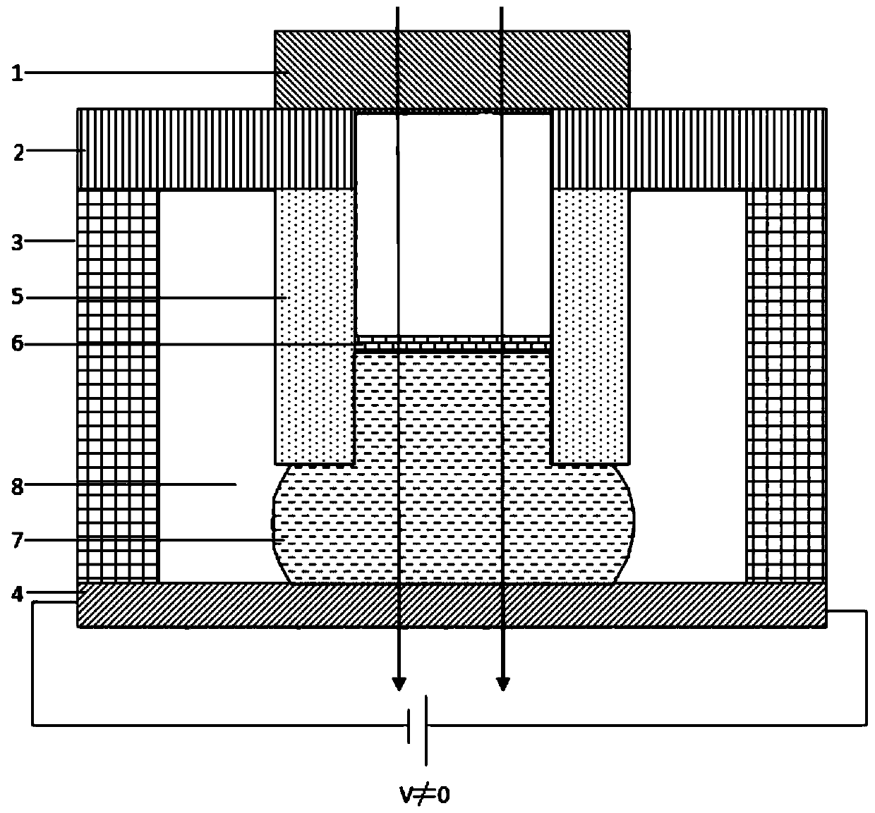
[0046] Step 1. Apply a voltage to the planar electrode, and the second liquid moves toward the center of the phase modulation device driven by the dielectric force, so that the contact angle and height of the first liquid increase, and the interface between the first liquid and the second liquid moves upward, as figure 2 As shown; when the voltage decreases, the dielectric force decreases, the contact angle and height of the first liquid decrease, and the interface between the first liquid and the second liquid moves downward;
[0047] Step 2, according to Calculate the phase difference change of the beam propagating from top to bottom, and finally complete the phase modulation,
[0048] Among them: ΔΦ represents the phase difference, Δ(ΔΦ) represents the amount of phase difference change, n 1 Indicates the first liquid refractive inde...
PUM
| Property | Measurement | Unit |
|---|---|---|
| thickness | aaaaa | aaaaa |
| diameter | aaaaa | aaaaa |
Abstract
Description
Claims
Application Information
 - R&D Engineer
- R&D Manager
- IP Professional
- Industry Leading Data Capabilities
- Powerful AI technology
- Patent DNA Extraction
Browse by: Latest US Patents, China's latest patents, Technical Efficacy Thesaurus, Application Domain, Technology Topic, Popular Technical Reports.
© 2024 PatSnap. All rights reserved.Legal|Privacy policy|Modern Slavery Act Transparency Statement|Sitemap|About US| Contact US: help@patsnap.com