Continuum structure topology and shape dimension comprehensive optimization method

An optimization method and continuum technology, applied in design optimization/simulation, geometric CAD, etc., can solve problems that affect optimization results and cannot describe the internal evolution process of structures favorably

Pending Publication Date: 2020-04-17
INST OF OPTICS & ELECTRONICS - CHINESE ACAD OF SCI
View PDF21 Cites 15 Cited by
  • Summary
  • Abstract
  • Description
  • Claims
  • Application Information

AI Technical Summary

Problems solved by technology

However, the level set method evolves the boundary contour of the continuum structure, and cannot describe the internal evolution process of the structure favorably. It needs to create many internal holes

Method used


Image

  • Continuum structure topology and shape dimension comprehensive optimization method
  • Continuum structure topology and shape dimension comprehensive optimization method
  • Continuum structure topology and shape dimension comprehensive optimization method

Examples


Embodiment 1

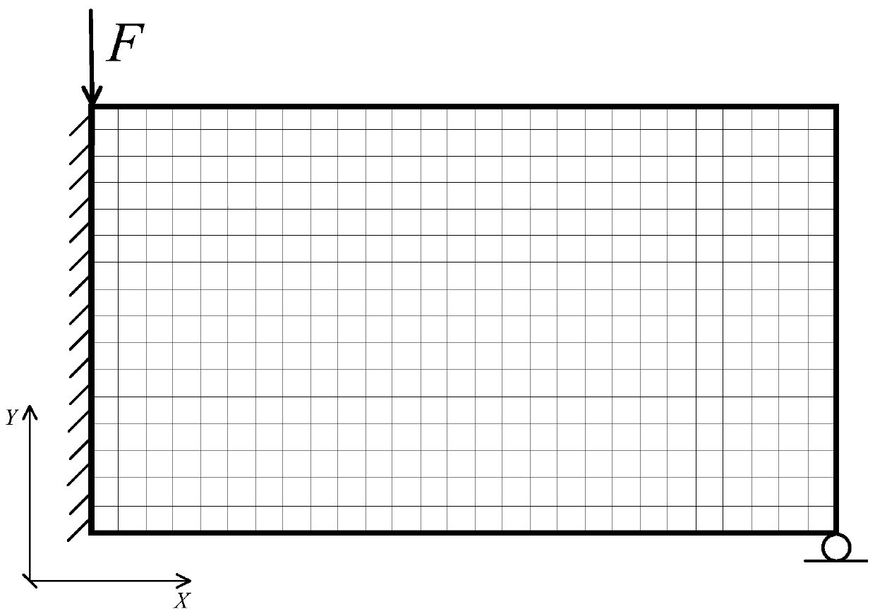
[0055] In this embodiment, the description of the optimal design process is carried out with a two-dimensional rectangular design domain as the object. It is set, but not limited to, that the Young's modulus E of the material is equal to 1 MPa, the Poisson's ratio μ is equal to 0.3, the length of the design domain is 60 mm, and the height is 30 mm.

[0056] In this example, if figure 2 As shown, according to step S1 to step S3, the rectangular design domain is divided into finite element meshes to obtain unit node information, and the left side of the rectangular design domain is fixedly connected to limit the degrees of freedom in all directions. In the lower right corner of the rectangular design domain Limit the movement in the Y direction, and impose a load constraint F equal to 1kN along the negative Y direction at the upper left corner of the rectangular design domain.

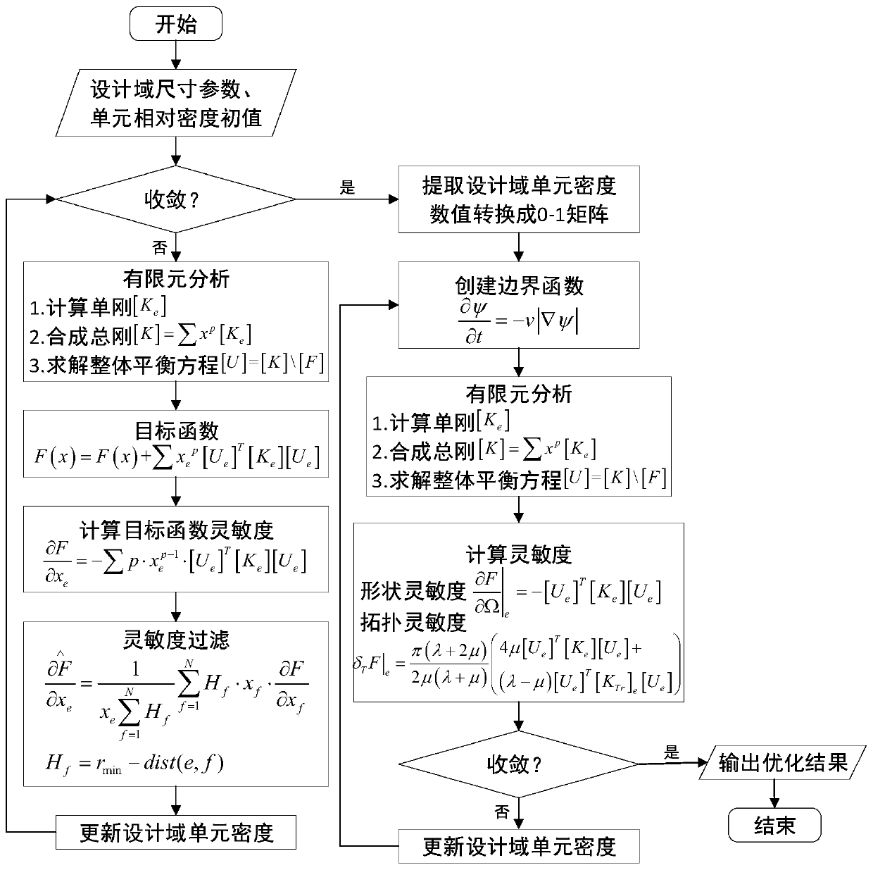
[0057] In this embodiment, according to steps S2 to S5, structural topology optimization is perform...

Embodiment 2

[0061] In this embodiment, the initial design conditions of Embodiment 1 are used as the optimization object, but the position and form of constraints and loads imposed on the design domain are changed, such as Image 6 shown. According to steps S1 to S3, the rectangular design domain is divided into finite element meshes to obtain unit node information, and the lower left corner of the rectangular design domain is fixedly connected to limit the degrees of freedom in all directions, and the lower right corner of the rectangular design domain is slid Connect to limit the degree of freedom in the Y direction, and impose a load constraint F equal to 1kN along the negative Y direction at the middle of the bottom edge of the rectangular design domain.

[0062] In this embodiment, according to steps S2 to S5, structural topology optimization is performed on the design domain to obtain a topological configuration with gray-scale units and internal holes, such as Figure 7 shown. Ho...


PUM


Abstract

The invention relates to a continuum structure topology and shape dimension comprehensive optimization method. The method comprises the steps of meshing a design domain by utilizing a finite element thought and extracting node information of a unit; creating an optimization objective function, adding constraints and loads, and iteratively updating the relative density value of the design domain unit by calculating the sensitivity of the objective function and completing sensitivity filtering; when it is judged that the convergence condition is met, outputting a topological structure with a gray level unit; then setting the numerical value of a gray scale unit to be 1, and meanwhile, filling tiny holes in the structure to form an initial topological structure in a discrete 0-1 matrix form;introducing a boundary function to optimize the shape and size of the initial topological configuration, and finally obtaining an optimal design structure meeting constraint conditions. According to the method, the influence of a gray scale unit on the structure manufacturability in traditional topological optimization is solved, meanwhile, a boundary function is introduced to optimize the shape and size of the initial topological configuration so as to eliminate fine holes embedded into the structure, and the complexity of the continuum structure in the manufacturing process is reduced.

Description

technical field [0001] The invention relates to the related technical field of structure optimization design, in particular to a method for comprehensive optimization of topology and shape and size of continuum structure. Background technique [0002] In the topology optimization design of the continuum structure, the commonly used methods are the density method based on the idea of ​​finite element and the level set method based on the idea of ​​boundary propagation. [0003] The topology optimization based on the density method divides the design domain of the continuum structure into a finite number of units, and assigns the relative density value to each unit as the variable of the optimal design. If the relative density value of the unit is discretized into a step function description of 0-1, and the unit is deleted or generated according to a certain evolution ratio, the optimization result obtained will always depend on the density of the grid, and to a large extent ...

Claims


Application Information

Patent Timeline
IPC IPC(8): G06F30/10G06F30/23
Inventor 张军峰刘恩海廖靖宇朱自发杨金利雷华舟
Owner INST OF OPTICS & ELECTRONICS - CHINESE ACAD OF SCI
Why Eureka
Try Eureka