Direct current interruption device
A technology for cutting off device and direct current, which is applied in the direction of DC network circuit device, circuit device, emergency protection circuit device, etc., and can solve problems such as complex structure and so on.
- Summary
- Abstract
- Description
- Claims
- Application Information
AI Technical Summary
Problems solved by technology
Method used
Image
Examples
no. 1 approach
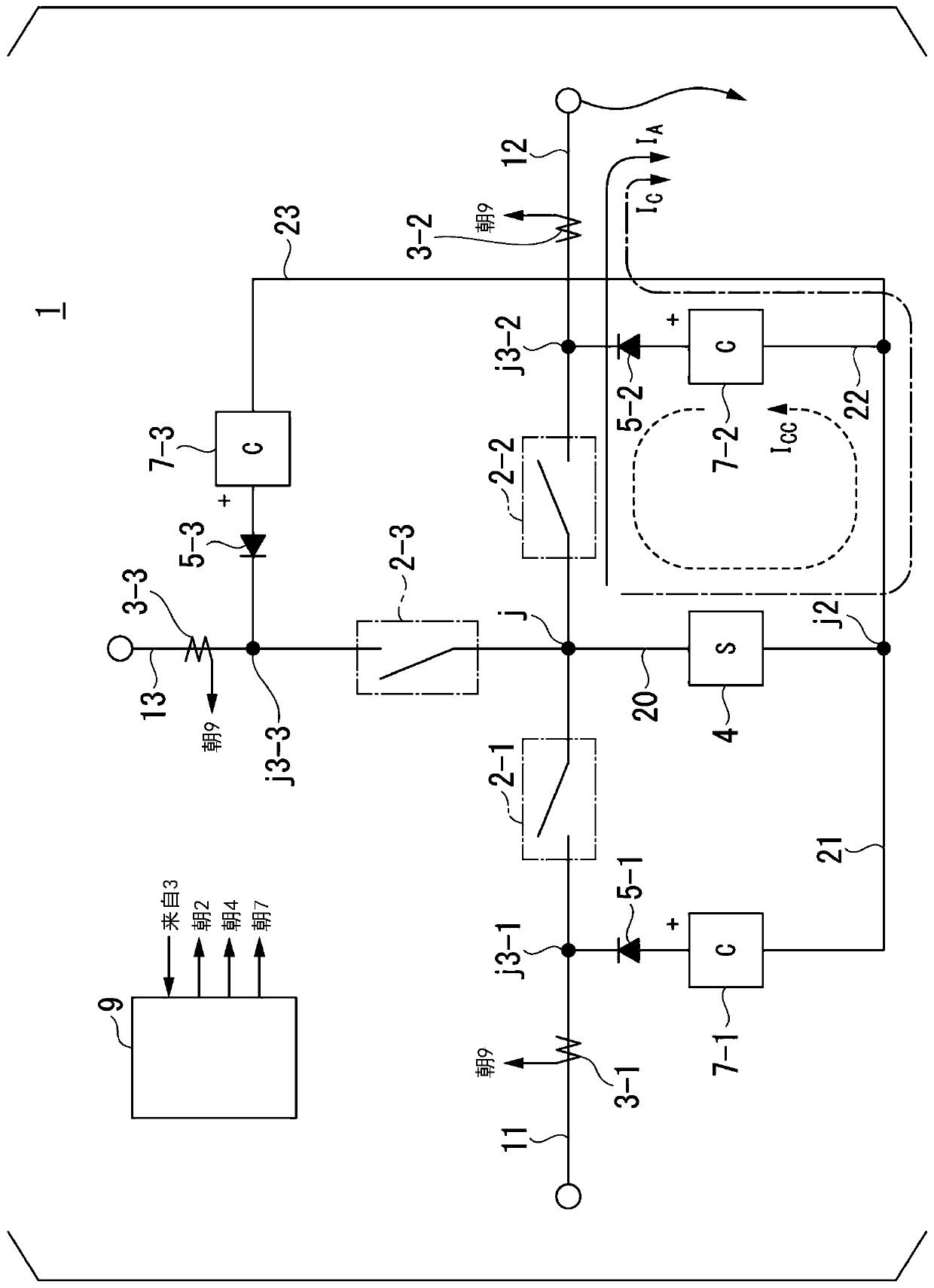
[0028] refer to figure 1 The DC current interrupter according to the first embodiment will be described. figure 1 It is a configuration diagram of the DC current interrupter according to the embodiment.
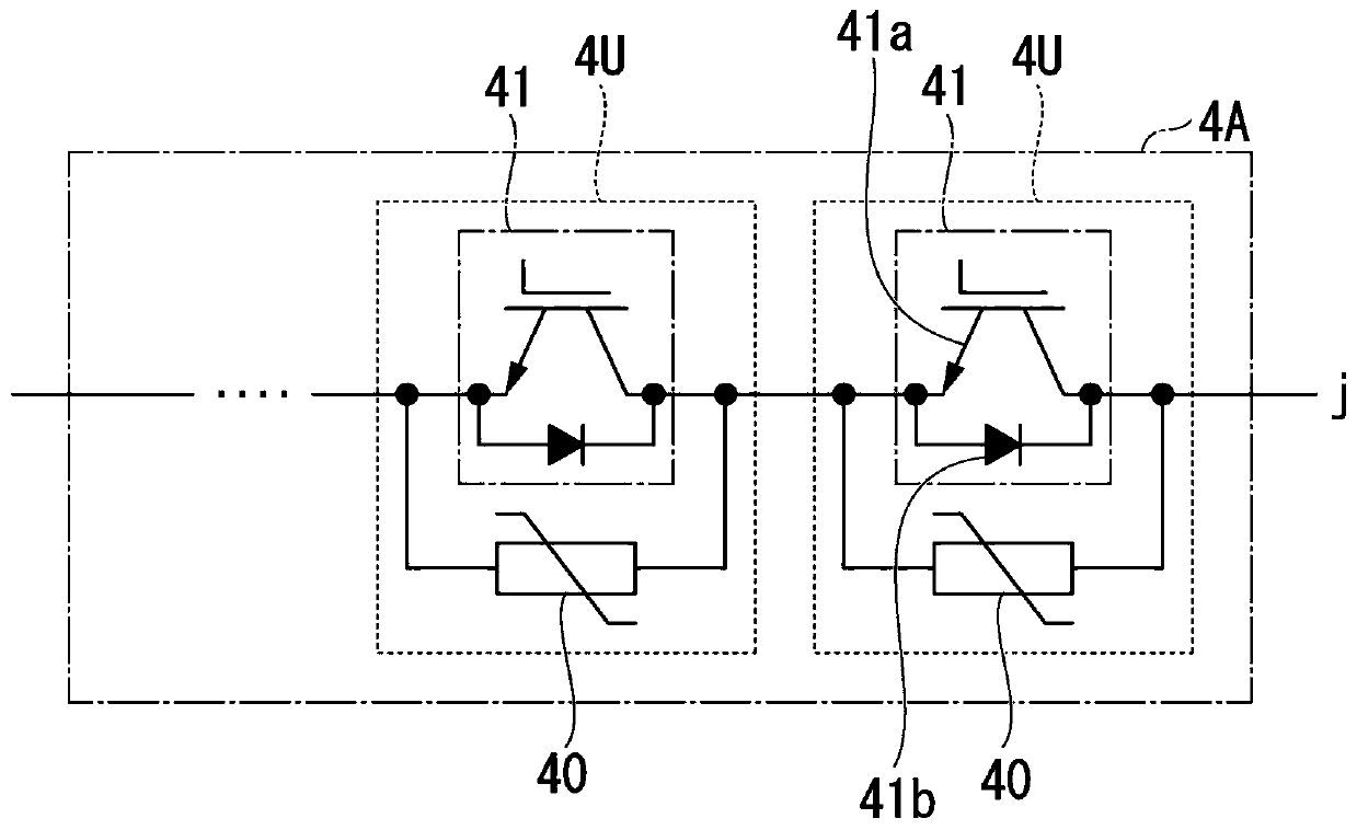
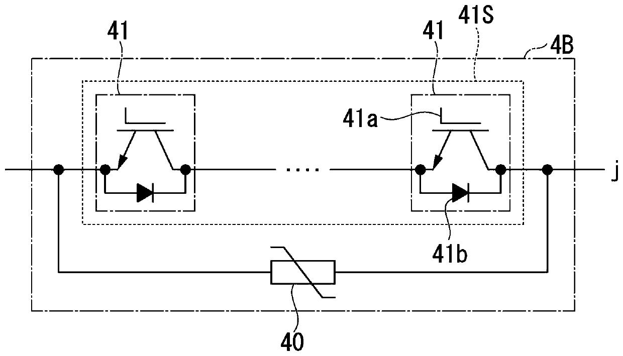
[0029] figure 1 The shown DC current interrupter 1 includes: mechanical circuit breakers 2-1 to 2-3, converters 3-1 to 3-3, semiconductor interrupter (S) 4, rectifier device (rectifier element) 5-1 to 5-3, converter device (C) 7-1 to 7-3, control unit 9 . In addition, mechanical circuit breakers 2 - 1 to 2 - 3 are examples of mechanical contact type circuit breakers.
[0030] The direct current transmission circuit to which the direct current interruption device 1 is applied includes the direct current transmission lines 11 to 13 and a node j (first node) to which the direct current transmission lines 11 to 13 are electrically joined. The direct current transmission lines 11 to 13 respectively correspond to the three systems, and are electrically connected to each other a...
no. 2 approach
[0104] refer to Figure 4 A direct current interruption device according to a second embodiment will be described. Figure 4 It is a configuration diagram of the DC current interrupter according to the embodiment. with figure 1 The differences will be explained centering on.
[0105] Figure 4 The shown DC current cutoff device 1 includes: mechanical circuit breakers 2-1 to 2-3, converters 3-1 to 3-3, semiconductor breakers 4-1 to 4-3, rectifier device 5, commutator Device 7, control unit 9.
[0106] The direct current transmission circuit to which the direct current interruption device 1 is applied includes the direct current transmission lines 11 to 13 and a node j2 (first node) to which the direct current transmission lines 11 to 13 are electrically joined.
[0107] The DC current interrupter 1 further includes a common auxiliary line 20 , an auxiliary line 21 (first auxiliary line), an auxiliary line 22 (second auxiliary line), and an auxiliary line 23 (third auxiliar...
no. 3 approach
[0124] refer to Figure 5 and Figure 6 A direct current interruption device according to a third embodiment will be described. Figure 5 It is a configuration diagram of the DC current interrupter according to the embodiment. with figure 1 The differences will be explained centering on.
[0125] Figure 5 The shown DC current cutoff device 1 includes: mechanical circuit breakers 2-1 and 2-2, converters 3-1 and 3-2, semiconductor breakers 4, rectifiers 5-1 and 5-2, commutation Devices 7 - 1 and 7 - 2 , control unit 9 , and converter 10 . In addition, the converter 10 may be a device external to the DC current cutoff device 1 .
[0126] The DC transmission circuit to which the DC current interrupter 1 is applied includes the DC transmission lines 11 , 12 , 14 and a node j (first node) to which the DC transmission lines 11 , 12 , 14 are electrically connected.
[0127] The DC current interrupter 1 further includes a common auxiliary line 20 , an auxiliary line 21 (first a...
PUM
 Abstract
Description
Claims
Application Information
 - R&D Engineer
- R&D Manager
- IP Professional
- Industry Leading Data Capabilities
- Powerful AI technology
- Patent DNA Extraction
Browse by: Latest US Patents, China's latest patents, Technical Efficacy Thesaurus, Application Domain, Technology Topic, Popular Technical Reports.
© 2024 PatSnap. All rights reserved.Legal|Privacy policy|Modern Slavery Act Transparency Statement|Sitemap|About US| Contact US: help@patsnap.com


