
Automatic machining device for automobile flange yoke

A technology of automatic processing and flange fork, which is applied to other manufacturing equipment/tools, manufacturing tools, etc., and can solve problems such as labor, time-consuming and labor-intensive

Active Publication Date: 2020-04-21
安徽艾德河汽车部件有限公司
View PDF7 Cites 6 Cited by
  • Summary
  • Abstract
  • Description
  • Claims
  • Application Information

AI Technical Summary

Problems solved by technology

[0002] The flange fork is one of the important key parts connected with the spline shaft in the automobile transmission system, which transmits the torque of the engine and bears the combined bending load. At present, the transmission system of trucks, heavy trucks, buses and other vehicles all over the world is The flange fork is used as the key transmission part. In the production process of the flange fork, it is forged and formed on the die forging equipment through pre-forging and final forging processes to form the initial embryo of the flange fork, and then the initial embryo of the flange fork is processed. Subsequent processing, in the subsequent processing of the initial blank of the flange fork, it is necessary to drill the initial blank of the flange fork. Drilling is carried out with a drilling machine. In the existing technology, two kinds of equipment are required to operate, and manual conversion is required, which is time-consuming and laborious. Therefore, we propose an automatic processing equipment for automobile flange forks to facilitate the solution the questions raised above

Method used


Image

  • Automatic machining device for automobile flange yoke
  • Automatic machining device for automobile flange yoke
  • Automatic machining device for automobile flange yoke

Examples


Embodiment Construction

[0028] In order to make the object, technical solution and advantages of the present invention clearer, the present invention will be further described in detail below in conjunction with the accompanying drawings and embodiments. It should be understood that the specific embodiments described here are only used to explain the present invention, not to limit the present invention.

[0029] In the description of the present invention, it should be noted that the terms "center", "upper", "lower", "left", "right", "front", "rear", "vertical", "horizontal", The orientation or positional relationship indicated by "inner", "outer", etc. is based on the orientation or positional relationship shown in the drawings, and is only for the convenience of describing the present invention and simplifying the description, rather than indicating or implying that the referred device or element must have Certain orientations, constructed and operative in certain orientations, therefore are not t...


PUM


Abstract

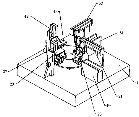
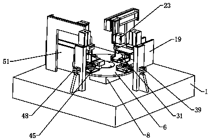
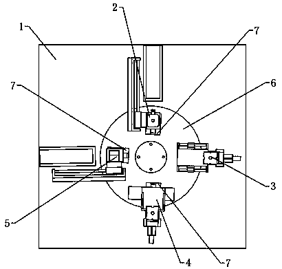
The invention relates to the technical field of automobile flange yoke machining, and particularly relates to an automatic machining device for an automobile flange yoke. The automatic machining device comprises a machining table and further comprises a rotary positioning mechanism, a feeding mechanism, a milling mechanism, a bidirectional drilling mechanism and a discharging mechanism, wherein the rotary positioning mechanism comprises a rotary disc and four positioning assemblies capable of clamping workpieces correspondingly; an index plate is arranged below the rotary disc; the bottom of the index plate is fixedly connected with the table top of the machining table; the output end of the index plate is fixedly connected with the center of the bottom of the rotary disc; the four positioning assemblies are evenly distributed at the edge of the top of the rotary disc in the circumferential direction of the rotary disc; the feeding mechanism, the milling mechanism, the bidirectional drilling mechanism and the discharging mechanism are arranged on the table top of the machining table; and the output end of the feeding mechanism, the output end of the milling mechanism, the output end of the bidirectional drilling mechanism and the output end of the discharging mechanism are in butt joint with the output ends of the positioning assemblies correspondingly. By means of the equipment, the primary blank machining position of the flange yoke can be automatically milled and drilled, and the machining efficiency is improved.

Description

technical field [0001] The invention relates to the technical field of automobile flange fork processing, in particular to an automatic processing equipment for automobile flange forks. Background technique [0002] The flange fork is one of the important key parts connected with the spline shaft in the automobile transmission system, which transmits the torque of the engine and bears the combined bending load. At present, the transmission system of trucks, heavy trucks, buses and other vehicles all over the world is The flange fork is used as the key transmission part. In the production process of the flange fork, it is forged and formed on the die forging equipment through pre-forging and final forging processes to form the initial embryo of the flange fork, and then the initial embryo of the flange fork is processed. Subsequent processing, in the subsequent processing of the initial blank of the flange fork, it is necessary to drill the initial blank of the flange fork. ...

Claims


Application Information

Patent Timeline
Patent Type & Authority Applications(China)
IPC IPC(8): B23P23/02
CPCB23P23/02
Inventor 丁童
Owner 安徽艾德河汽车部件有限公司
Learn More