
Steel-concrete composite beam containing corrugated connecting pieces and implementation method thereof

A technology of connectors and composite beams, applied in bridges, bridge parts, bridge materials, etc., can solve the problems of steel plate fatigue cracks, heavy workload, and increase the complexity of construction, so as to improve crack resistance, reduce welding area, The effect of convenient construction

Active Publication Date: 2020-04-21
SOUTHEAST UNIV
View PDF14 Cites 4 Cited by
  • Summary
  • Abstract
  • Description
  • Claims
  • Application Information

AI Technical Summary

Problems solved by technology

At present, welding studs are still the most used connection method, but a large number of welding studs not only requires a lot of work, but also introduces a large amount of welding residual stress on the steel plate, which is easy to cause fatigue cracks in the steel plate under the action of fatigue load
Conventional open-hole plate connectors are welded open-hole steel plates on steel beams. The construction is relatively simple. In order to further increase the shear stiffness, steel bars are generally inserted into the round holes, which increases the complexity of construction and the workload. larger

Method used


Image

  • Steel-concrete composite beam containing corrugated connecting pieces and implementation method thereof
  • Steel-concrete composite beam containing corrugated connecting pieces and implementation method thereof
  • Steel-concrete composite beam containing corrugated connecting pieces and implementation method thereof

Examples


Embodiment Construction

[0031] The present invention will be further described below in conjunction with accompanying drawing and embodiment:

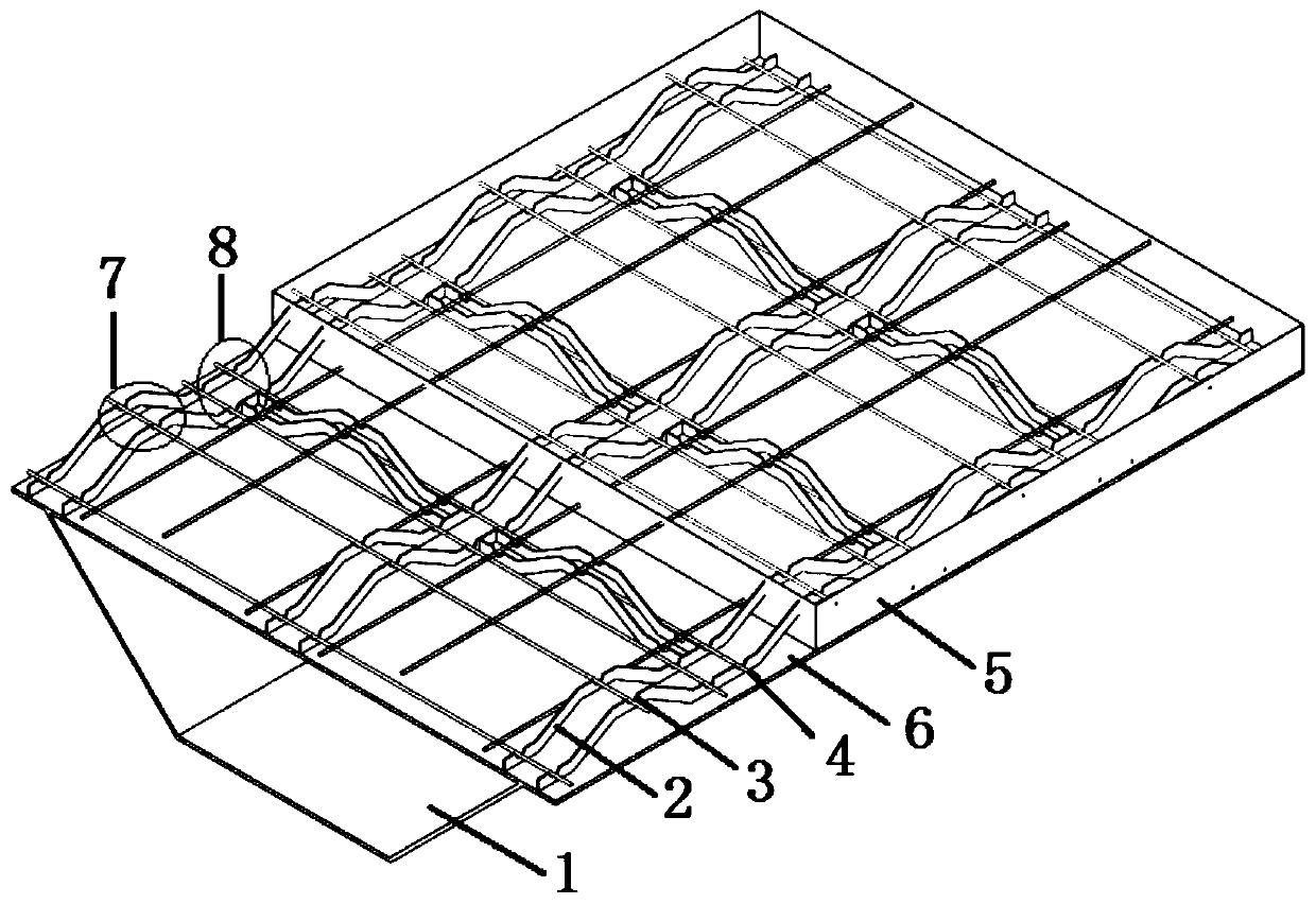
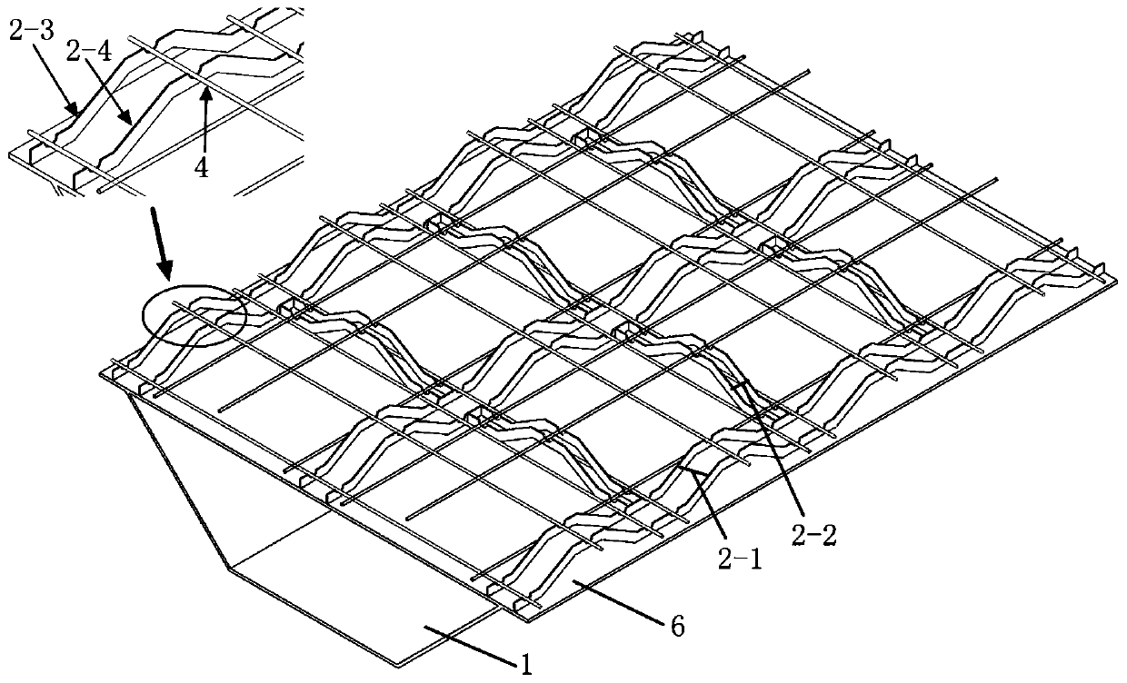
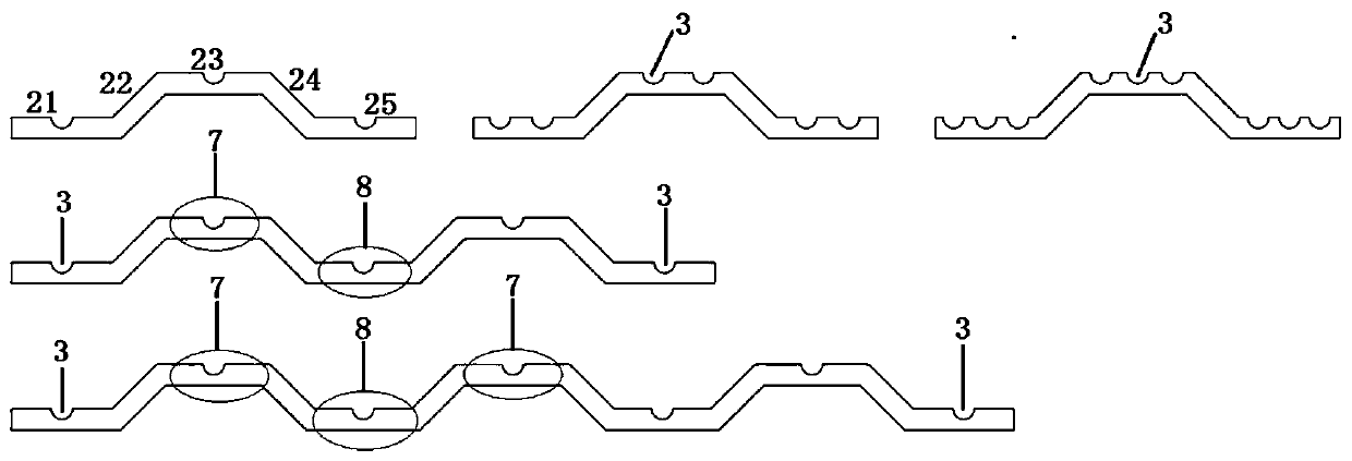
[0032] Such as figure 1 As shown, a steel-concrete composite beam with corrugated connectors in this embodiment includes a steel beam 1, a corrugated connector 2 welded to the upper panel 6 of the steel beam and through steel bars 4; wherein the corrugated connector 2 Each group of two is used to arrange the corrugated connectors 2 in groups in the longitudinal and transverse directions of the upper panel 6 of the steel beam, and the corrugated connectors 2 are distributed in strips; wherein the corrugated connectors Part 2 is provided with openings 3 at the peaks 7 and troughs 8, wherein the penetrating steel bar 4 passes through the openings 3, and the upper part of the upper panel 6 of the steel beam is poured with high-performance fiber concrete 5, and the high-performance fiber concrete 5 is wrapped The corrugated connector 2 and the penetrating steel b...


PUM


Abstract

The invention discloses a steel-concrete composite beam containing corrugated connecting pieces and an implementation method thereof, and belongs to a steel-concrete composite structure. The steel-concrete composite structure comprises a steel beam, corrugated connecting pieces welded to an upper panel of the steel beam and penetrating steel bars; every two corrugated connecting pieces form a group, and the corrugated connecting pieces are arranged in groups in the longitudinal direction and the transverse direction of an upper panel of the steel beam respectively and distributed in a strip-shaped mode; open holes are formed in the wave crests and the wave troughs of the corrugated connecting pieces, the penetrating steel bars penetrate through the open holes, a layer of the penetrating steel bars are arranged at the wave crests, and a layer of the penetrating steel bars are arranged at the wave troughs in an upper-lower double-layer steel bar arrangement mode; high-performance fiberconcrete is poured on the upper portion of the upper panel of the steel beam and is used for wrapping the corrugated connecting pieces and the penetrating steel bars to form a composite shearing forcepiece. The steel structure is small in welding workload, convenient to construct, high in working efficiency, small in welding residual stress, high in bearing capacity and good in fatigue resistance.

Description

technical field [0001] The invention relates to the technical field of bridge structures, in particular to a steel-concrete composite beam with corrugated connectors and an implementation method thereof. Background technique [0002] The steel-concrete composite structure refers to the combination of concrete and steel materials through a certain connection method, and the correct use of the respective advantages of the two materials to form a more reasonable structural system. The joint surface of the two materials is subjected to complex forces, and the realization of reliable connection is particularly important for the overall mechanical performance of the combined structure. [0003] The connection forms of the joint surface of the steel-concrete composite structure mainly include chemical cement, welding studs, section steel connectors, and perforated steel plate connectors. Due to their different structures and construction performance, various connectors have their ...

Claims


Application Information

Patent Timeline
Patent Type & Authority Applications(China)
IPC IPC(8): E01D2/04E01D19/12E01D21/00
CPCE01D2/04E01D19/125E01D21/00E01D2101/26E01D2101/266E01D2101/30
Inventor 王文炜李霞惠迎新周畅薛彦杰郑宇宙黄辉田俊李杉尹世平
Owner SOUTHEAST UNIV
Learn More