Combined heat storage unit

A combined heat storage technology, which is applied in heat storage equipment, indirect heat exchangers, heat exchange equipment, etc., can solve the problem that dusty flue gas cannot be dedusted, and achieves easy installation and maintenance, low height, and good uniformity Effect

Pending Publication Date: 2020-04-21
思安新能源股份有限公司
View PDF0 Cites 0 Cited by
  • Summary
  • Abstract
  • Description
  • Claims
  • Application Information

AI Technical Summary

Problems solved by technology

[0006] The purpose of the present invention is to provide a combined heat storage unit to solve the problem that existing heat storage equipment cannot remove dust when exchanging heat with dusty flue gas

Method used


Image

  • Combined heat storage unit
  • Combined heat storage unit
  • Combined heat storage unit

Examples


Embodiment Construction

[0028] The present invention will be described in detail below in conjunction with the accompanying drawings and specific embodiments.

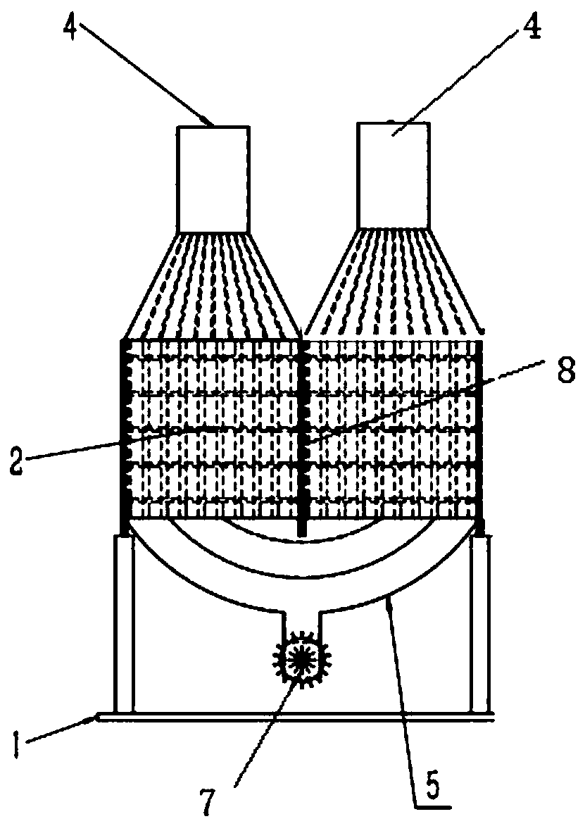
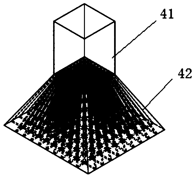
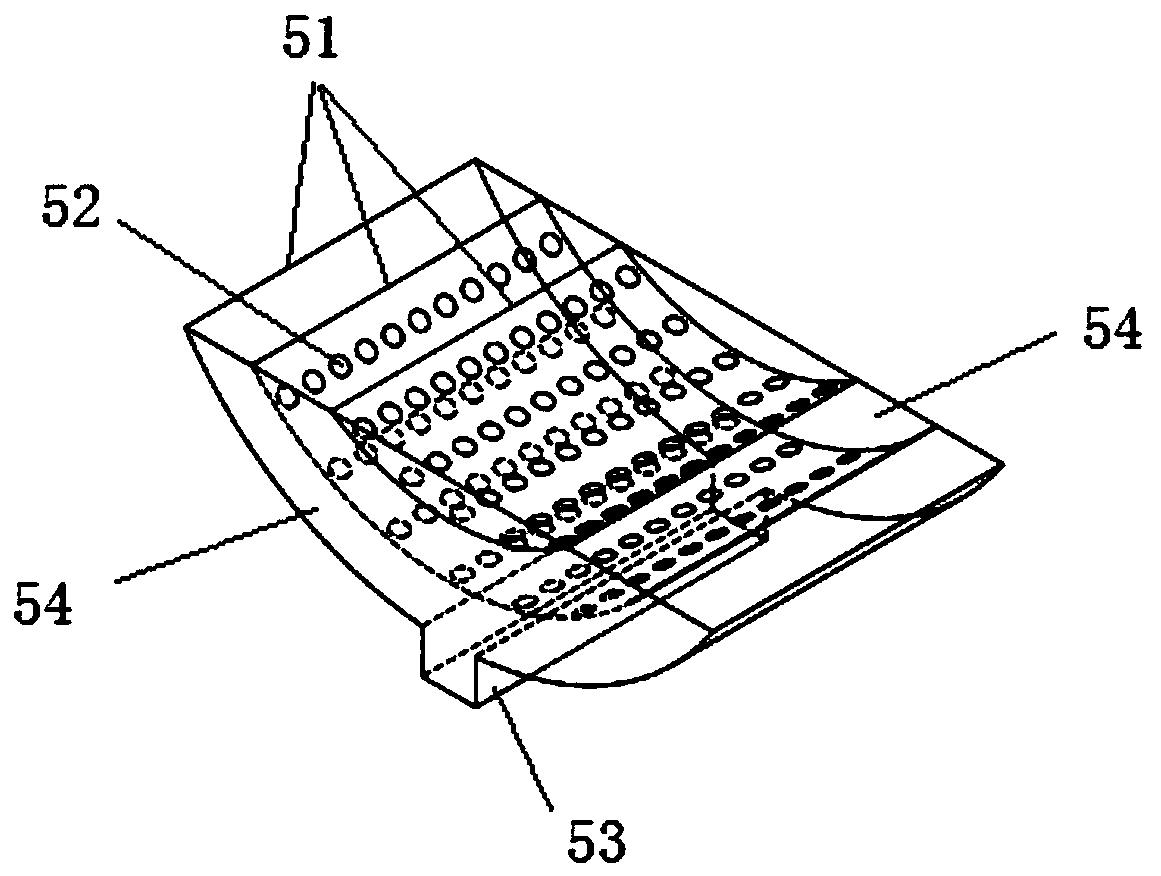
[0029] The invention provides a combined heat storage unit, such as figure 1 As shown, it includes a heat storage device 2 fixed on the base support 1 and an ash discharge channel 5 arranged at the bottom of the heat storage device 2 . Two independent heat exchange spaces are arranged side by side in the heat storage device 2 , and the top of each heat exchange space is provided with an opening for gas to pass through. The ash discharge channel 5 is arranged at the bottom of the heat storage device 2 for connecting the two heat exchange spaces, and the bottom of the middle section of the ash discharge channel 5 is provided with an ash unloading valve 7 downward. Among them, one heat exchange space, the ash discharge channel 5 and the other heat exchange space constitute the gas flow channel in turn, each of the heat exchange spaces is used t...


PUM


Abstract

The invention discloses a combined type heat storage unit which comprises a heat storage device and an ash discharging channel. Two independent heat exchange spaces are arranged in the heat storage device in parallel, and an opening allowing gas to pass through is formed in the top of each heat exchange space; the ash discharging channel is arranged at the bottom of the heat storage device and used for communicating the two heat exchange spaces, and an ash discharging valve is arranged at the bottom of a middle section of the ash discharging channel; one heat exchange space, the ash dischargechannel and the other heat exchange space sequentially form a gas flowing channel, each heat exchange space is used for storing heat or releasing heat for gas, the ash discharge channel is used for providing a deposition space for dust in the gas, and the ash discharging valve is used for discharging deposited dust. The problems that existing heat storage equipment is mainly suitable for clean gasand dust cannot be discharged during heat exchange of dusty flue gas are solved.

Description

【Technical field】 [0001] The invention belongs to the technical field of heat storage equipment, and in particular relates to a combined heat storage unit. 【Background technique】 [0002] Existing gas heat storage equipment mainly includes regenerative hot blast stoves, electric heat storage equipment, and heat storage equipment in combined cycle gas turbine (CCGT) power plants. [0003] The hot blast stove is used in the iron and steel industry to increase the temperature of the pre-combustion air. It has a burner on the top or side. When charging, the gas after burning the gas is used as the heat source. It is relatively clean. The heat storage part is directly used for the Blockages can occur in dusty fumes. [0004] Electric heat storage products use electric heating rods to directly heat the air when charging, and the temperature of the heat source reaches 1000°C. When releasing heat, the temperature of hot water produced by the air-water heat exchanger is less than 10...

Claims


Application Information

Patent Timeline
Patent Type & Authority Applications(China)
IPC IPC(8): F28D20/00F28F19/01B01D45/02
CPCB01D45/02F28D20/0056F28D2020/0065F28F19/01Y02E60/14
Inventor 王志雄陈久林倪瑞涛段洋刘刚
Owner 思安新能源股份有限公司
Why Eureka
Try Eureka