
Self-monitoring electrical device and elevator circuit

An electrical device and self-monitoring technology, which is applied to electrical components, parts of electrical measuring instruments, circuits, etc., can solve problems such as unstable operation of equipment, high resistance of contact positions, and poor contact of switch contacts, so as to reduce investigation work Effect

Pending Publication Date: 2020-04-21
李勇
View PDF0 Cites 0 Cited by
  • Summary
  • Abstract
  • Description
  • Claims
  • Application Information

AI Technical Summary

Problems solved by technology

[0003] In real life, it can be found that after a long period of use, the contact position of the switch will be oxidized, carbon black, etc., and some switches will be deformed, so the switch contact has poor contact, the resistance of the contact position is too large, and it is close to failure. Critical point, causing unstable operation of equipment (short-term failures occur from time to time, and then recover by themselves; manifested as potential / hidden failures)
Faults appear in a catch-and-seek manner, causing circuit faults in a short period of time, and the circuit is restored when maintenance personnel check or prepare to check
If maintenance personnel go to troubleshoot, it will take a lot of time

Method used


Image

  • Self-monitoring electrical device and elevator circuit
  • Self-monitoring electrical device and elevator circuit
  • Self-monitoring electrical device and elevator circuit

Examples


Embodiment Construction

[0026] Embodiments of the present invention are described in detail below, and examples of the embodiments are shown in the drawings, wherein the same or similar reference numerals denote the same or similar elements or elements having the same or similar functions throughout. The embodiments described below by referring to the figures are exemplary only for explaining the present invention and should not be construed as limiting the present invention.

[0027] In the description of the present invention, unless otherwise clearly defined, words such as setting, installation, and connection should be understood in a broad sense, and those skilled in the art can reasonably determine the specific meanings of the above words in the present invention in combination with the specific content of the technical solution.

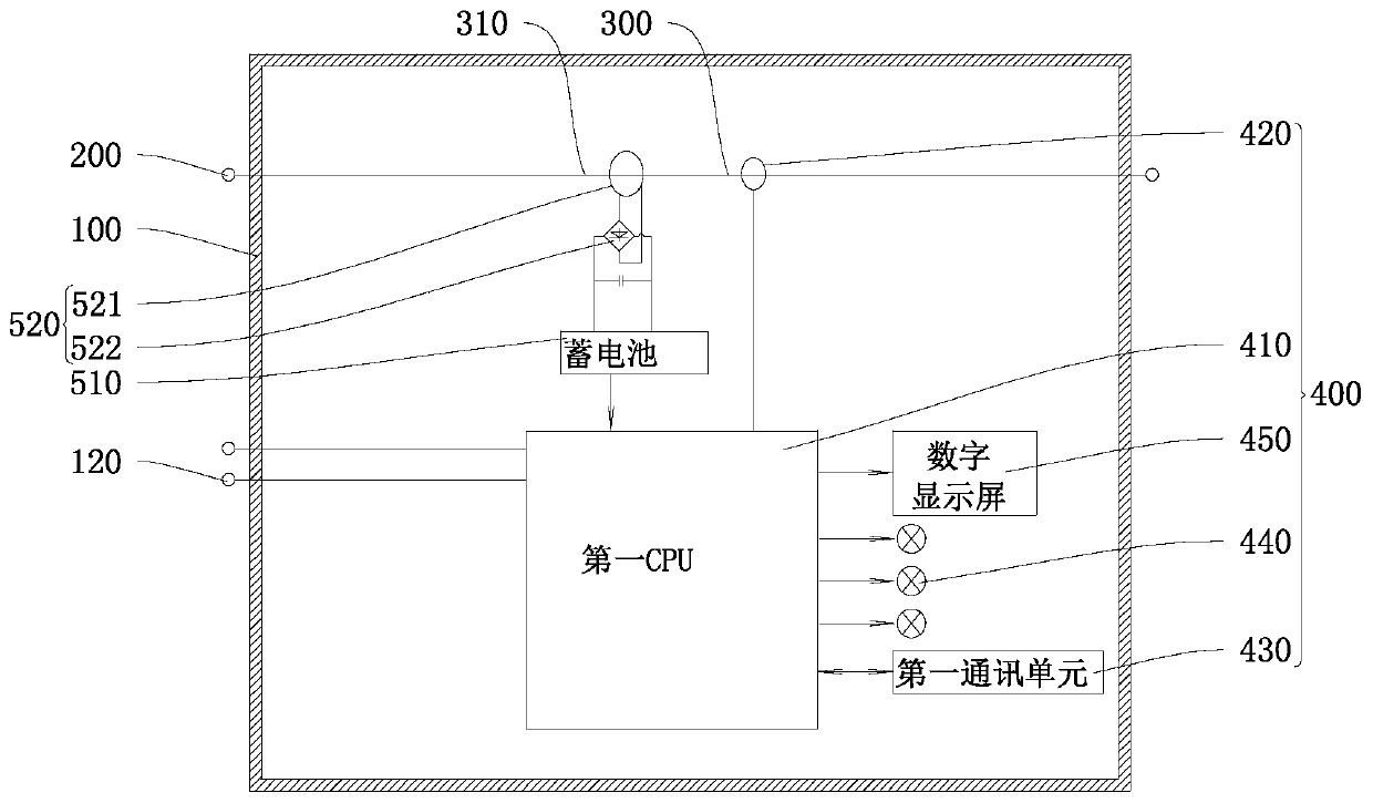
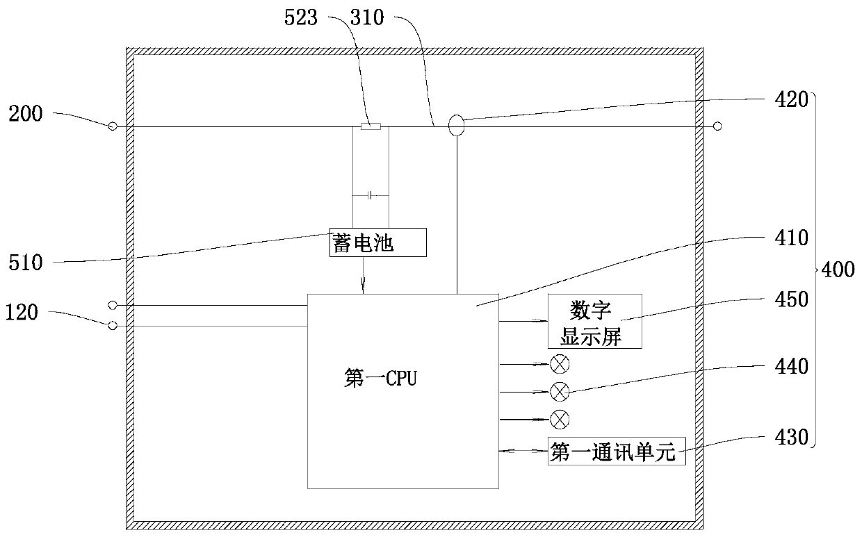
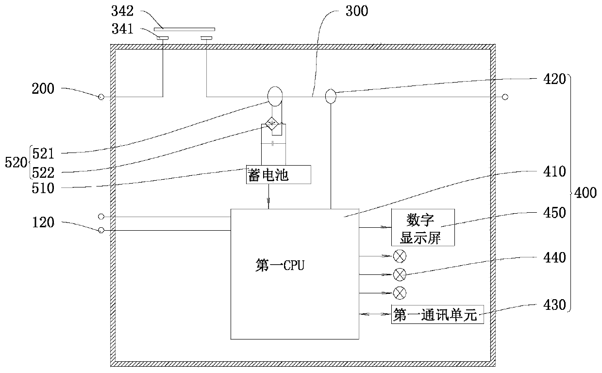
[0028] refer to figure 1 , a self-monitoring electrical device according to the embodiment of the first aspect of the present invention, including a housing 100, a f...


PUM


Abstract

The invention discloses a self-monitoring electrical device, which comprises a shell, first wiring terminals, a tested circuit and a signal processing circuit; the tested circuit is connected betweenthe two first wiring terminals; the signal processing circuit is arranged in the shell and comprises a first CPU and a detection probe connected with the first CPU, the detection probe is used for detecting a detected circuit, and the first CPU is further electrically connected with a first communication unit and / or an alarm. Devices corresponding to the signal processing circuit and the tested circuit are integrated in the shell, and in actual use, only the first wiring terminals need to be connected. A self-monitoring electrical device is used as a link of a circuit. When the circuit in thelink has a potential hidden fault, the detection probe detects the potential hidden fault and informs the first CPU and the first communication unit to inform external equipment or give an alarm, theabnormality can be quickly found, a maintainer directly starts maintenance from the abnormal position, the fault searching procedure is omitted, and people are prevented from being trapped by the potential hidden fault of the elevator in the field of elevators.

Description

technical field [0001] The invention relates to electrical components, in particular to a self-monitoring electrical device. Background technique [0002] The switch can be independently an electrical component. According to functional classification, switches can be divided into detection switches, knob switches, key switches, etc.; according to the on-off device under normal conditions, switches can be divided into normally open switches and normally closed switches. Switches can also be found in electrical components such as relays and contactors; electrical components such as relays and contactors include switches and coils. [0003] In real life, it can be found that after a long period of use, the contact position of the switch will be oxidized, carbon black, etc., and some switches will be deformed, so the switch contact has poor contact, the resistance of the contact position is too large, and it is close to failure. Critical point, causing unstable operation of th...

Claims


Application Information

Patent Timeline
Patent Type & Authority Applications(China)
IPC IPC(8): G01R31/327G01R1/04G05B19/042B66B5/02B66B13/14H01H15/02H01H15/06
CPCB66B5/02B66B13/143G01R1/0408G01R1/0416G01R31/3277G01R31/3278G05B19/0425H01H15/02H01H15/06
Inventor 李勇
Owner 李勇
Learn More