
Operation microscope

A surgical microscope and beam splitter technology, applied in microscopes, optics, instruments, etc., can solve the problems that microscopes cannot have both high resolution and large depth of field, and achieve a reduced sense of depth, good use comfort, and satisfaction The effect of application requirements

Inactive Publication Date: 2020-04-21
ZHEJIANG FUTURE TECH INST JIAXING
View PDF7 Cites 5 Cited by
  • Summary
  • Abstract
  • Description
  • Claims
  • Application Information

AI Technical Summary

Problems solved by technology

[0003] For this reason, the embodiment of the present invention provides an operating microscope to solve the problem that existing operating microscopes cannot have both high resolution, large depth of field and comfort in use

Method used


Image

  • Operation microscope
  • Operation microscope
  • Operation microscope

Examples


Embodiment 1

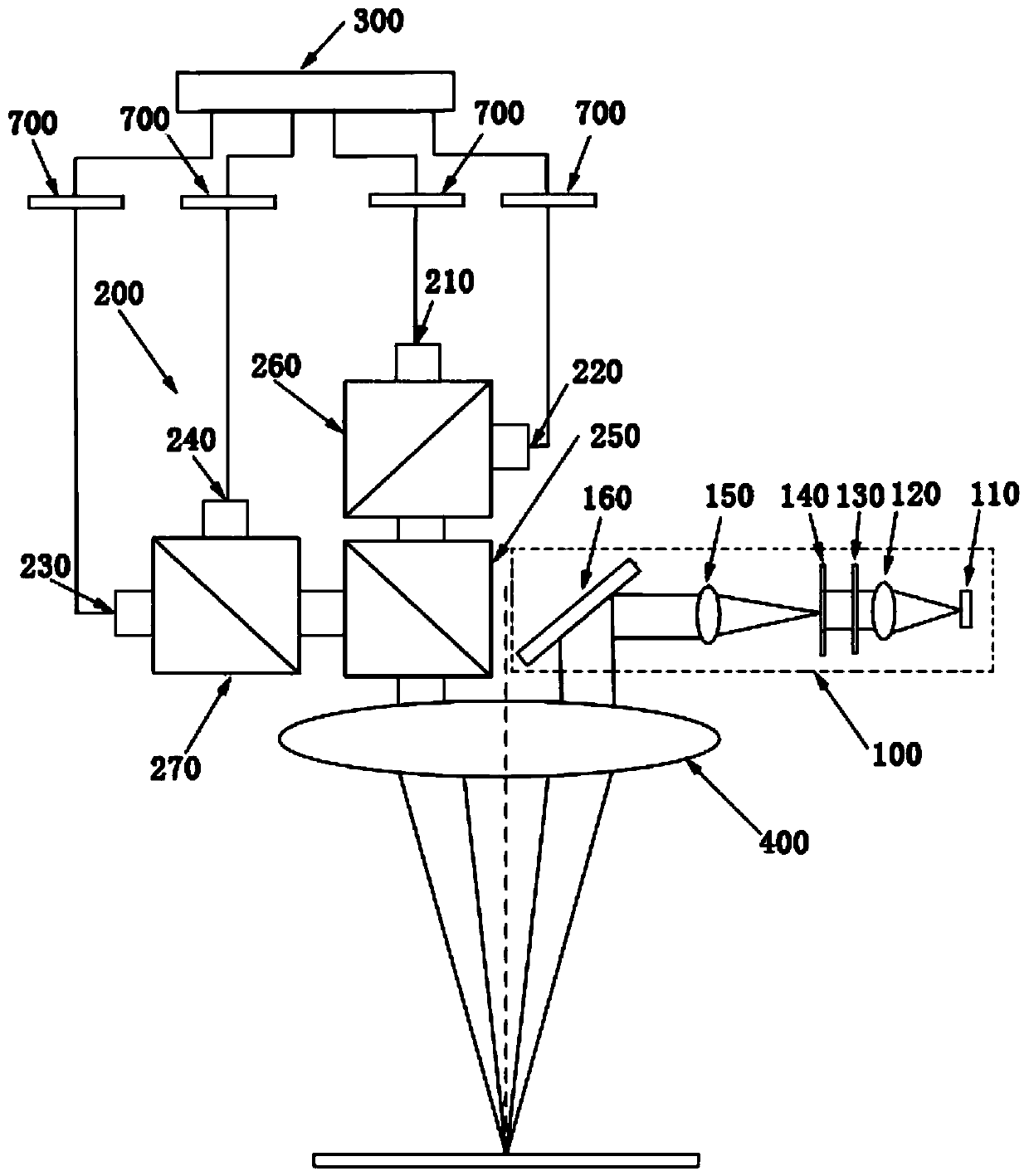
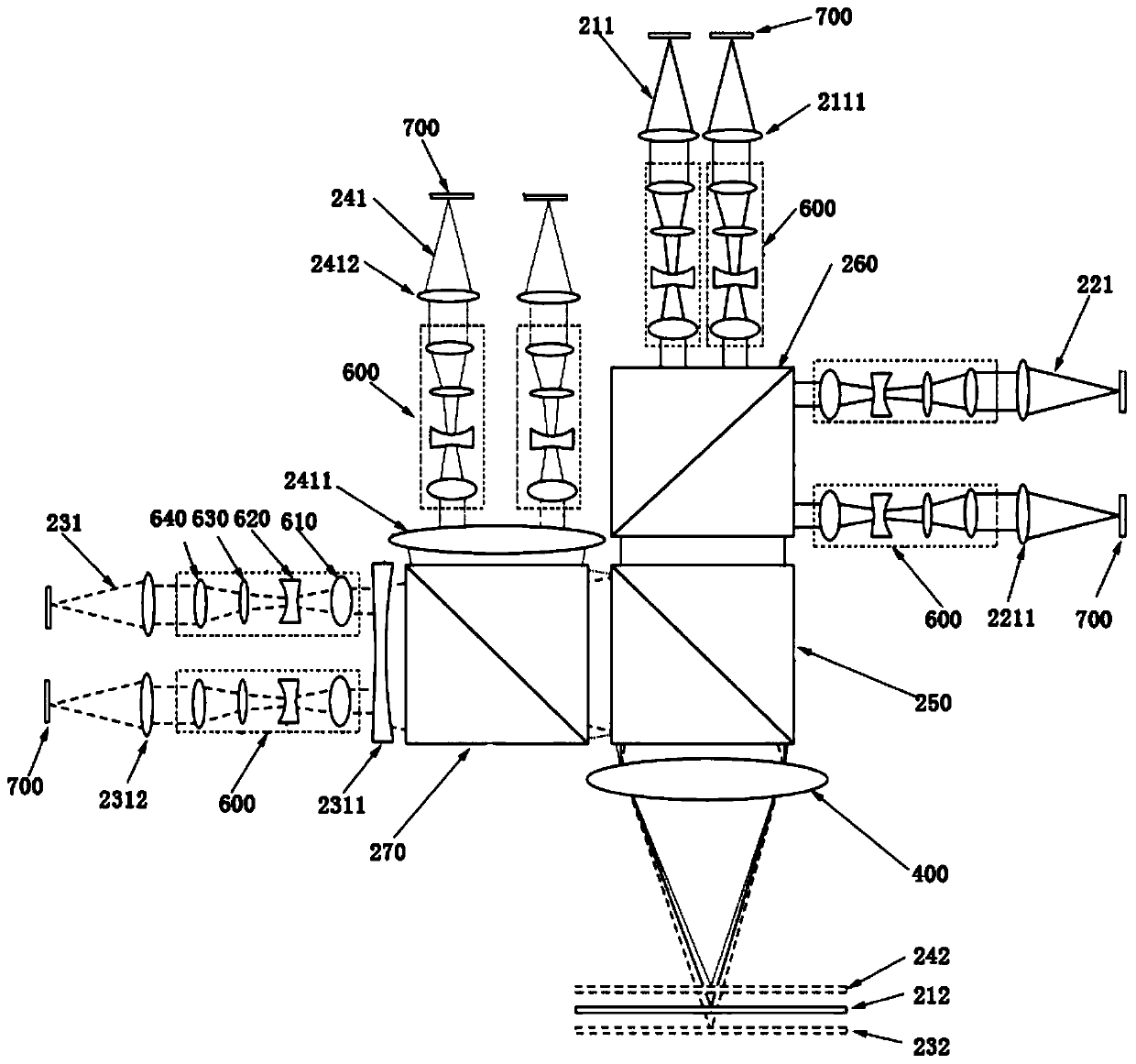
[0026] This embodiment proposes a surgical microscope, such as figure 1 As shown, the surgical microscope includes an illumination system 100 , an imaging system 200 and an image processing system 300 .

[0027] The illumination system 100 is used to provide a uniform illumination field of view that meets imaging requirements for the object under the imaging objective lens 400 .

[0028] Specifically, the lighting system 100 includes a light source 110, a condenser lens 120, a filter 130, an aperture 140, a projection objective lens 150, and a reflector 160 arranged in sequence. After 120, it is parallel light output and reaches the diaphragm 140 after passing through the optical filter 130. The diaphragm 140 is located at the aperture diaphragm 140 of the condenser 120 and the front focal plane of the projection objective lens 150. The illuminance on the surface of the diaphragm 140 is uniform, and the optical The size of the diaphragm 140 can change the diameter of the illu...


PUM


Abstract

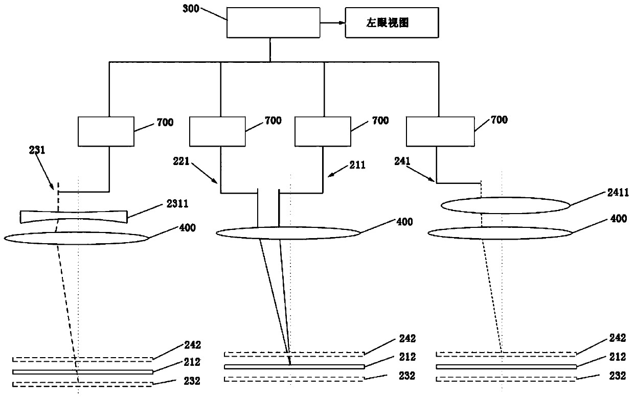
The embodiment of the invention discloses an operation microscope. The operation microscope comprises an illumination system, an imaging system and an image processing system, wherein a plurality of optical imaging subsystems are adopted for imaging at the same time, different optical imaging systems correspond to different imaging functions, a left eye view and a right eye view which are large indepth of field and high in resolution are obtained through fusion calculation of the multi-light-path multifunctional images, the two images are subjected to 3D interweaving, and the finally obtainedobject 3D image is obviously reduced in depth and effectively improved in definition and has the characteristics of large depth of field and high resolution. Meanwhile, the microscope also has good use comfort and can well meet the application requirements of doctors.

Description

technical field [0001] Embodiments of the present invention relate to the technical field of surgical microscopes, in particular to a surgical microscope. Background technique [0002] As a conventional medical equipment, the operating microscope has been widely used in various surgical operations such as ophthalmology, ENT, neurosurgery, and dentistry. The doctor uses the operating microscope to observe the tiny details of the patient's wound. The ability of the microscope to distinguish details and the comfort of operation have a great impact on the success rate of the doctor's operation. In order to reduce the impact, the resolution and comfort of the operating microscope must be improved. In this regard, surgical microscope engineers have carried out long-term and effective explorations. For example, in terms of microscope comfort, using 3D cameras to replace traditional visual systems, doctors can directly watch the screen for surgery without the need for surgeon mirro...

Claims


Application Information

Patent Timeline
IPC IPC(8): G02B21/00G02B21/06G02B21/18G02B21/36G02B21/02G02B21/22
CPCG02B21/0012G02B21/025G02B21/06G02B21/18G02B21/22G02B21/367
Inventor 邵航廖家胜阮程张亚龙张新
Owner ZHEJIANG FUTURE TECH INST JIAXING
Learn More