Adapter connector

A technology for adapting connectors and connecting ends, which is applied in the directions of connection, installation of connecting components, and components of connecting devices, etc., can solve the problems of poor tolerance between connectors and printed boards, inconvenient assembly and maintenance, etc., and achieve the layout method. Optimized, the overall structure is easy to maintain, and the structure is simple.

Pending Publication Date: 2020-04-21
CHINA AVIATION OPTICAL-ELECTRICAL TECH CO LTD
View PDF0 Cites 3 Cited by
  • Summary
  • Abstract
  • Description
  • Claims
  • Application Information

AI Technical Summary

Problems solved by technology

[0007] The purpose of the present invention is to provide a transfer connector, which can solve the problems of poor toleran

Method used


Image

  • Adapter connector
  • Adapter connector
  • Adapter connector

Examples


Embodiment 1

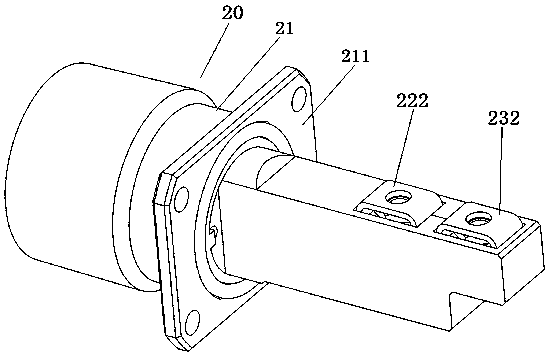
[0045] Embodiment 1 of the transfer connector in the present invention: the transfer connector in the present invention is used to realize the conduction of the internal and external circuits of the equipment, and the plug-in end of the transfer connector is mated with the adapter plug in the external circuit, and the transfer The connection end of the connector is used to connect with the printed board in the device to realize the transmission of electrical signals. like image 3 As shown, the transfer connector 20 includes a housing 21, the housing 21 is made of insulating material, a square plate 211 is arranged on the outer peripheral surface of the housing 21, and a fastener perforation is provided on the square plate 211 for bolts to pass through. Can be fixedly connected with the equipment housing. A contact piece is arranged in the housing 21, and the contact piece can be press-fitted with the printed board contact piece on the printed board 30 as a conductive compone...

Embodiment 2

[0064] Embodiment 2 of the transfer connector in the present invention: the difference from the above embodiment is that, as Image 6As shown, in the transfer connector 60 of this embodiment, the housing 61 is provided with an installation cavity and two contact pieces. A spring 63 as an elastic supporting structure is installed between the first cantilever of the two contact pieces 62 and the cavity wall of the installation cavity, and the two ends of the spring 63 support the outer surface of the contact piece 62 and the cavity wall respectively. Wherein, the cavity wall that supports and cooperates with the end of the spring 63 is a straight wall extending along the insertion direction of the transfer connector 60 , which can stably support the spring 63 .

[0065] When the contact piece 62 swings, the spring 63 can deform along with the swing of the contact piece 62 , and the spring 63 can provide a force to the contact piece 62 to press the contact piece 62 to the conduct...

Embodiment 3

[0066] Embodiment 3 of the transfer connector in the present invention: the difference from the above embodiments is that the overhanging part of the contact in this embodiment is in the shape of a line, and the overhanging part extends obliquely to the conductive component in the printed board. The extension direction of the connection end is parallel to the insertion direction, and the overhang part is inclined to lift the crimp end, so that the crimp end is closer to the conductive component; or the end of the inline overhang part is bent backward at least twice Get crimp ends that are angled or U-shaped, with the entire overhang scooped. Of course, the function of the overhanging part is to realize the swing of the contact piece, and the shape of the overhanging part can also adopt a serpentine shape or other shapes that will not affect the swinging.


PUM


Abstract

The invention relates to an adapter connector. With the adapter connector adopted, the problems of poor tolerance capacity and inconvenient assembly and maintenance during the connection of a connector and a printed board in the prior art can be solved. The adapter connector comprises a shell, a contact piece and a threaded locking sleeve; the front end of the shell is a connecting end; the rear end of the shell is a plugging end; the contact piece is fixed in the shell; the contact piece comprises an overhanging part extending forwards; the front end of the overhanging part is a crimping endconnected with a conductive part in an equipment box body; the crimping end is in crimping connection with the conductive part in a direction perpendicular to a plugging direction; an avoidance spacefor allowing the overhanging part to deform in a crimping direction is formed in a position, corresponding to the overhanging part, in the shell; the threaded locking sleeve is located on the inner side of the crimping end; and a through hole is formed in the crimping end, corresponds to an inner hole of the threaded locking sleeve and is used for allowing an adaptive locking piece to penetrate through, so that the adaptive locking piece drives the threaded locking sleeve to act, and the crimping end and the conductive part are connected in a pressed mode.

Description

technical field [0001] The invention relates to the technical field of connectors, in particular to a transfer connector. Background technique [0002] In the prior art, some devices are fixed with printed boards. In order to connect the printed boards in the equipment box with the circuit outside the equipment box, an external socket is generally installed on the box wall of the equipment box, and then through the transfer The connected conductive parts connect the external socket with the printed board to realize power or signal transmission. like figure 1 and figure 2 As shown, it is the structure of the connection between the printed board and the external circuit in the prior art: a printed board 14 is arranged in the equipment box, and the positions of the printed board 14 and the equipment box are relatively fixed, and the printed board 14 is welded or Other ways are fixedly connected to the printed board connector 13, the printed board connector 13 includes an in...

Claims


Application Information

Patent Timeline
IPC IPC(8): H01R13/621H01R13/24H01R13/516H01R13/74H01R31/06
CPCH01R13/2442H01R13/516H01R13/621H01R13/74H01R31/06
Inventor 刘向阳邹宏飞李立新胡竣浩李晓月王恒
Owner CHINA AVIATION OPTICAL-ELECTRICAL TECH CO LTD
Why Eureka
Try Eureka