
Pipe welding machine with welding slag cleaning function

A welding machine and welding mechanism technology, applied in welding equipment, welding equipment, auxiliary welding equipment, etc., can solve problems such as low efficiency and lack of welding slag cleaning function, and achieve improved bonding effect, improved cleaning effect, and improved general-purpose sexual effect

Active Publication Date: 2020-04-24
上海中巽科技股份有限公司
View PDF11 Cites 9 Cited by
  • Summary
  • Abstract
  • Description
  • Claims
  • Application Information

AI Technical Summary

Problems solved by technology

Similarly, the same as manual welding, the welding machine will inevitably produce welding slag when welding pipes, and most of the existing welding machines do not have the function of cleaning the welding slag, and it is necessary to clean the welding slag after the welding is completed, which is more efficient. low

Method used


Image

  • Pipe welding machine with welding slag cleaning function
  • Pipe welding machine with welding slag cleaning function
  • Pipe welding machine with welding slag cleaning function

Examples


Embodiment 1

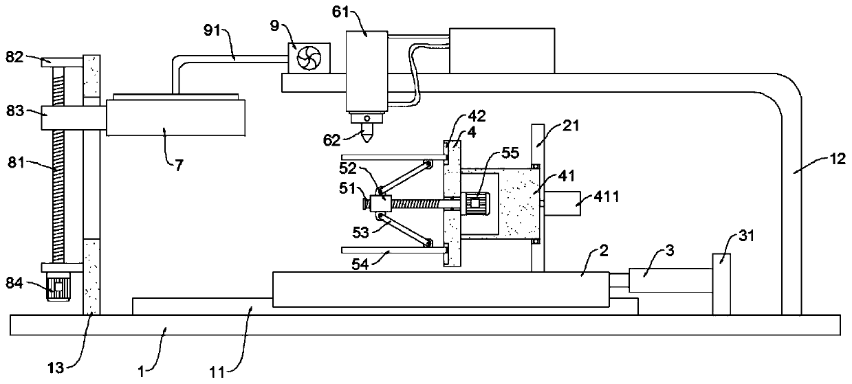
[0021] see Figure 1~3 , in an embodiment of the present invention, a pipe welding machine with the function of removing welding slag includes a base 1, a moving base 2, a rotating base 4 and a welding mechanism; the top of the base 1 is fixed with a support frame 12, and the welding mechanism is installed on On the support frame 12; the moving base 2 is slidably connected to the slide rail 11 fixed on the base 1 and driven by a traversing drive mechanism, the moving base 2 is fixed with a mounting plate 21, and the rotating base 4 is connected to the mounting plate 21 through a connecting block 41 in rotation , the connection block 41 is driven by a rotating motor 411, and a clamping mechanism is installed on the rotating seat 4. When in use, the pipe is fixed by the clamping mechanism, and then the pipe is driven by the traverse drive mechanism to move to the bottom of the welding mechanism, and then the rotating The motor 411 drives the pipe to rotate, and then the pipe is ...

Embodiment 2

[0030] see figure 1 and 4 , the embodiment of the present invention describes the clamping mechanism in detail on the basis of embodiment 1, specifically:

[0031] Described clamping mechanism comprises adjusting screw mandrel 51 and a plurality of ejector rods 54, and adjusting screw mandrel 51 is rotatably connected with swivel seat 4, and the adjusting motor 55 that drives adjusting screw mandrel 51 is installed on the swivel seat 4, and the rod body periphery of adjusting screw mandrel 51 A sleeve 52 matching it is sheathed; a plurality of ejector rods 54 are equidistantly arranged on the periphery of the adjusting screw rod 51 along the circumferential direction, and one end of the ejector rod 54 is slidably locked in the chute 42 opened on the rotating disk 4 Among them, a connecting rod 53 is hinged on the inner surface of the ejector rod 54, and the end of the connecting rod 53 is hinged to the sleeve 52. When working, the adjusting motor 55 drives the adjusting screw...


PUM


Abstract

The invention discloses a pipe welding machine with a welding slag cleaning function. A base, a moving base, a rotation base and a welding mechanism are included. A supporting frame is fixed to the top of the base, and the welding mechanism is arranged on the supporting frame. The moving base is in sliding connection with a sliding rail fixed to the base and is driven through a transverse moving driving mechanism. An installing plate is fixed to the moving base, the rotation base is rotationally connected with the installing plate through a connecting block, the connecting block is driven by arotation motor, and the rotation base is provided with a clamping mechanism. A supporting plate is further fixed to the base and provided with a grinding piece. The grinding piece is in sliding connection with the supporting plate and is driven by a lifting driving mechanism. According to the pipe welding machine, through the arrangement of the moving base, the rotation base, the transverse moving driving mechanism and the clamping mechanism, a pipe can rotate and can also transversely move, accordingly, on one hand, welding work can be effectively finished in cooperation with the welding mechanism, and on the other hand, the welding slag cleaning work can be conducted in cooperation with the grinding piece.

Description

technical field [0001] The invention relates to the field of welding technology, in particular to a pipe welding machine with the function of removing welding slag. Background technique [0002] As the name suggests, welding machine is a kind of mechanical equipment that replaces manual welding work, and it is widely used in the field of pipe processing. Similarly, the same as manual welding, the welding machine will inevitably produce welding slag when welding pipes, and most of the existing welding machines do not have the function of cleaning the welding slag, and it is necessary to clean the welding slag after the welding is completed, which is more efficient. low. Contents of the invention [0003] The object of the present invention is to provide a pipe welding machine with the function of removing welding slag, so as to solve the above problems. [0004] To achieve the above object, the present invention provides the following technical solutions: [0005] A pipe...

Claims


Application Information

Patent Timeline
IPC IPC(8): B23P23/00B23K31/02B23K37/00B24B9/04B24B55/06
CPCB23K31/02B23K37/00B23P23/00B24B9/04B24B55/06
Inventor 谭宁
Owner 上海中巽科技股份有限公司
Features
  • Generate Ideas
  • Intellectual Property
  • Life Sciences
  • Materials
  • Tech Scout
  • Unparalleled Data Quality
  • Higher Quality Content
  • 60% Fewer Hallucinations
Learn More