Circular pipe clamping and cutting device

A cutting device and a round tube technology, applied in metal processing, etc., can solve the problems of reduced work efficiency, high production cost, and increased user cost, and achieve the effects of preventing irregular cutting surfaces, wide application range, and good practicability

Pending Publication Date: 2020-04-24
天津鑫凯建业科技有限公司
View PDF0 Cites 2 Cited by
  • Summary
  • Abstract
  • Description
  • Claims
  • Application Information

AI Technical Summary

Problems solved by technology

In the prior art, a lathe is usually used to clamp the end of the pipe body, but the structure of the lathe is relatively complicated, the production cost is high, and the user's use cost is increased, and the operation during clamping is very complicated, which reduces the work efficiency
In addition, the existing round pipe cutting device cannot adjust the cutting length well as required, nor can it adjust the cutting position as required.

Method used

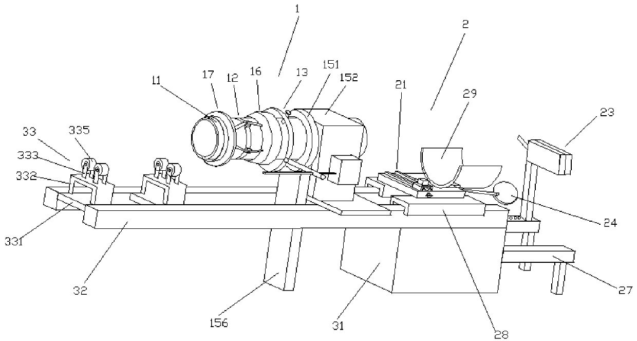
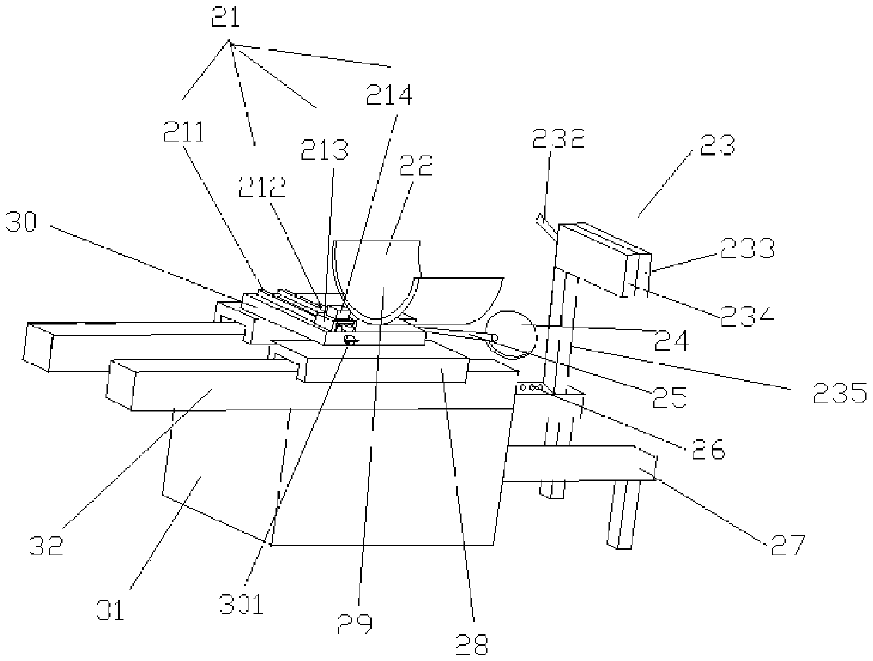
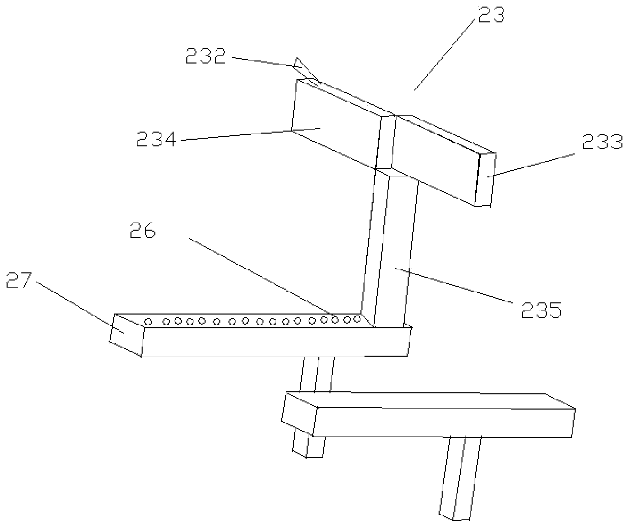

Image

  • Circular pipe clamping and cutting device
  • Circular pipe clamping and cutting device
  • Circular pipe clamping and cutting device

Examples


Embodiment Construction

[0048] It should be noted that, in the case of no conflict, the embodiments of the present invention and the features in the embodiments can be combined with each other.

[0049]In describing the present invention, it should be understood that the terms "center", "longitudinal", "transverse", "upper", "lower", "front", "rear", "left", "right", " The orientations or positional relationships indicated by "vertical", "horizontal", "top", "bottom", "inner" and "outer" are based on the orientations or positional relationships shown in the drawings, and are only for the convenience of describing the present invention and Simplified descriptions, rather than indicating or implying that the device or element referred to must have a particular orientation, be constructed and operate in a particular orientation, and thus should not be construed as limiting the invention. In addition, the terms "first", "second", etc. are used for descriptive purposes only, and should not be understood a...


PUM


Abstract

The invention provides a circular pipe clamping and cutting device which comprises guide beams. At least one guide support assembly is fixed at the front ends of the guide beams, the guide support assembly is located between the two guide beams, a clamping mechanism is fixed at the top of the middle end of the guide beam, a cutting mechanism is fixed at the tops of the rear ends of the guide beams, a base is fixed at the bottoms of the rear ends of the guide beams, a supporting cross beam is fixed on the side wall of the base, and a positioning assembly is connected to the top of the supporting cross beam. The circular pipe clamping and cutting device not only can adjust the cutting length as required, but also can adjust the cutting position as required, can clamp the end part of a circular pipe through a sliding assembly, the clamping assembly and a moving assembly which are matched with each other, and is high in practicability and wide in application range.

Description

technical field [0001] The invention belongs to the field of round pipe processing equipment, in particular to a round pipe clamping and cutting device. Background technique [0002] During the processing of the round pipe, it is usually necessary to cut the two ends of the round pipe flat, so as to ensure that the surfaces of the two ends of the pipe body are parallel, so the ends of the pipe body need to be clamped. In addition, the round pipe needs to be cut according to the requirements during the production and processing process. In the prior art, a lathe is usually used to clamp the end of the pipe body, but the structure of the lathe is relatively complicated, the production cost is high, and the user's use cost is increased, and the operation during clamping is very complicated, which reduces the work efficiency. In addition, the existing circular pipe cutting device cannot adjust the cutting length well as required, nor can it adjust the cutting position as requir...

Claims


Application Information

Patent Timeline
Patent Type & Authority Applications(China)
IPC IPC(8): B26D1/06B26D7/02B26D7/26
CPCB26D1/06B26D7/02B26D7/2628B26D2007/013
Inventor 王秀玲王俊普
Owner 天津鑫凯建业科技有限公司
Why Eureka
Try Eureka