Hydraulic Coal Bunker Arch Breaking Device

A coal bunker and arch breaking technology, which is applied in packaging, transportation and packaging, and large containers, can solve problems such as collapse, damage to the bin body, and collapse of the coal arch, so as to improve strength and elasticity, prolong service life, and avoid elasticity deformation effect

Active Publication Date: 2022-02-08
ZHENGZHOU UNIV
View PDF7 Cites 0 Cited by
  • Summary
  • Abstract
  • Description
  • Claims
  • Application Information

AI Technical Summary

Problems solved by technology

[0006] 1. Artificial arch breaking
[0007] After the coal bunker is arched, the staff manually use tools to insert the blockage in the bunker and poke it, causing the coal arch to sink
The disadvantage of this arch breaking method is that the manual labor intensity is high, and it needs someone to be on duty near the coal bunker, which cannot meet the needs of no one on duty at the coal bunker.
[0010] The disadvantages of this method of breaking the arch are: poor safety, long preparation time, and the phenomenon of collapsing the funnel or destroying the warehouse body, there are many unsafe factors
Its disadvantage is: if high-pressure water arch breaking is used as a regular means of arch breaking, it is necessary not to take the high-pressure water pipe out of the coal bunker after arch breaking
Because the outlet of the high-pressure water pipe is facing upward, there may be arching, so during the normal use of the coal bunker and the process of coal falling, loose coal and coal dust can easily enter the high-pressure water pipe, thereby blocking the high-pressure water pipe
Therefore, high-pressure water arch breaking is not suitable as a regular means of arch breaking, resulting in the fact that high-pressure water arch breaking is rarely used in practice

Method used


Image

  • Hydraulic Coal Bunker Arch Breaking Device
  • Hydraulic Coal Bunker Arch Breaking Device

Examples


Embodiment Construction

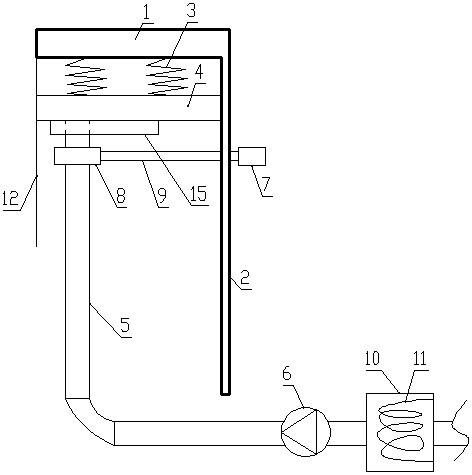
[0036] like figure 1 and figure 2 As shown, the hydraulic coal bunker arch breaking device of the present invention includes a mounting seat, the mounting seat includes a top plate 1 and a side wall 2 of the mounting seat connected to one side of the top plate 1, and the side wall 2 of the mounting seat is used to be installed on the coal bunker through the mounting frame. The bottom of the side wall; the installation frame and the coal bunker are all conventional technologies, not shown in the figure.

[0037] The top plate 1 is connected downward with at least one spring 3, the lower end of the spring 3 is connected with a cover plate 4 made of rubber or plastic, the lower part of the cover plate 4 is provided with a water spray pipe 5 with an opening upward, and the water spray pipe 5 is made of rubber , the cover plate 4 is used to prevent coal from falling into the spray pipe 5;

[0038] The water spray pipe 5 extends from the bottom of the mounting seat to the side wa...


PUM


Abstract

The invention discloses a hydraulic coal bunker arch breaking device, which comprises a mounting seat, the mounting seat includes a top plate and a side wall of the mounting seat connected below one side of the top plate; a spring is connected downward to the top plate, and a cover plate is connected to the lower end of the spring. There is a water spray pipe with the opening facing upward under the plate; the extension rod of the electric push rod slides through the side wall of the mounting seat and its end is connected with a power plate, and the top of the water spray pipe passes through the installation hole of the power plate; the water spray Driven by the electric push rod and power disc, the pipe has a water spray position and a storage position. When water spray is not needed, the water spray pipe can return to the bottom of the cover plate and the top of the water spray pipe is crimped with the cover plate, which is well avoided. The phenomenon that the coal in the coal bunker enters the water spray pipe in the storage state is prevented, so that the present invention can keep the water spray pipe from being blocked during long-term use, has strong arch breaking ability, and is suitable as a regular arch breaking device.

Description

technical field [0001] The invention relates to the technical field of underground coal transportation. Background technique [0002] The coal bunker is the main loading and storage link in the mine production system, which plays an important role in ensuring the quality of coal products, adjusting the unbalanced state of production and transportation, and ensuring the continuous and stable production of the mine. [0003] There is a conveyor (such as a scraper conveyor) under the coal bunker. When transferring coal, the coal in the bunker falls down on the conveyor. The coal bunkers in the mining area of ​​almost all mines are blocked to varying degrees in the process of production and use, and need to be dealt with frequently. This will not only fail to give full play to the role of the coal bunker, but seriously affect normal production. The most common form of coal bunker blockage is coal bunker arching. [0004] The coal temperature is lower in winter, and the coal c...

Claims


Application Information

Patent Timeline
Patent Type & Authority Patents(China)
IPC IPC(8): B65D88/70B65D90/48B65D90/00
CPCB65D88/70B65D90/48B65D90/00
Inventor 张建立李阳刘康康
Owner ZHENGZHOU UNIV
Why Eureka
Try Eureka