Shrinkage power-assisted damper

A technology of dampers and piston rods, which is applied in the direction of shock absorbers, shock absorbers, gas-hydraulic shock absorbers, etc., can solve the problems of insignificant boosting effect of compression springs, easy to pinch operators, narrow application range, etc., and achieve The effect of reducing failure risk, good economic benefits, and reducing development costs

Pending Publication Date: 2020-04-24
SUSPA (NANJING) CO LTD
View PDF0 Cites 3 Cited by
  • Summary
  • Abstract
  • Description
  • Claims
  • Application Information

AI Technical Summary

Problems solved by technology

The problems of the above-mentioned method are as follows: (1) The boosting effect produced by the compression spring is not obvious, and the scope of application is narrow
(2) Cooperating with the use of tension springs will increase the cost, and it is easy to pinch the operator during use

Method used


Image

  • Shrinkage power-assisted damper
  • Shrinkage power-assisted damper
  • Shrinkage power-assisted damper

Examples


Embodiment 1

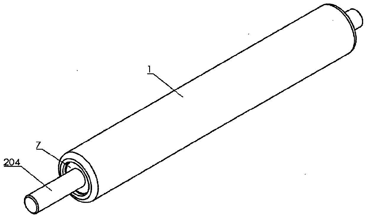
[0026] Such as figure 1 and figure 2 As shown, a contraction booster damper includes a cylinder 1 and a piston rod assembly 2 arranged inside the cylinder 1,

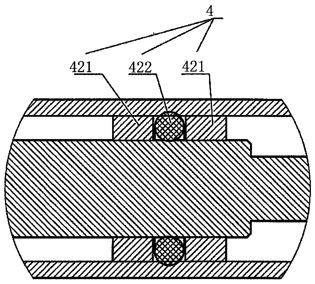
[0027] A sealing assembly 4 is fixed at a designated position in the middle of the cylinder 1, and the sealing assembly 4 is used to seal and separate the first cavity 3 and the second cavity 5. The piston rod assembly 2 includes a piston rod 204 and a pad fixed at the end Sheet 201, piston ring 202 and piston 203, the piston end of the piston rod 204 is set in the first cavity 3, the middle of which is set as a stepped step surface, and the stepped step surface is set in the second cavity 5 , the sealing assembly 4 is respectively sealed with the inner wall of the cylinder 1 and the large diameter of the piston rod 204;

[0028] The connection between the gasket 201 and the piston rod 204 is provided with a hole structure, and the end of the second cavity 5 is sealed by the air seal 6, and a guide block 7 is further...

Embodiment 2

[0037] Such as figure 1 and image 3 As shown, a contraction booster damper includes a cylinder 1 and a piston rod assembly 2 arranged inside the cylinder 1,

[0038] A sealing assembly 4 is fixed at a designated position in the middle of the cylinder 1, and the sealing assembly 4 is used to seal and separate the first cavity 3 and the second cavity 5. The piston rod assembly 2 includes a piston rod 204 and a pad fixed at the end Sheet 201, piston ring 202 and piston 203, the piston end of the piston rod 204 is set in the first cavity 3, the middle of which is set as a stepped step surface, and the stepped step surface is set in the second cavity 5 , the sealing assembly 4 is respectively sealed with the inner wall of the cylinder 1 and the large diameter of the piston rod 204;

[0039] The connection between the gasket 201 and the piston rod 204 is provided with a hole structure, and the end of the second cavity 5 is sealed by the air seal 6, and a guide block 7 is further ...


PUM


Abstract

The invention relates to a damper, in particular to a shrinkage power-assisted damper. The shrinkage power-assisted damper comprises a cylinder barrel and a piston rod component arranged inside the cylinder barrel, wherein a sealing component is fixed at a specified position of the middle of the cylinder barrel and is used for sealing and separating a first cavity and a second cavity; the piston rod component comprises a piston rod, a gasket, a piston ring and a piston, and the gasket, the piston ring and the piston are fixed at the tail end; the piston end of the piston rod is arranged in thefirst cavity; the middle of the piston rod is a stepped step surface; the stepped step surface is arranged in the second cavity; the sealing component is in large diameter sealing with the inner wallof the cylinder barrel and the piston rod; a hole-slot structure is arranged at a connecting part of the gasket and the piston rod; the tail end of the second cavity is sealed by an air seal; and a guide block is further arranged on the exterior of the air seal to perform revolving-riveting and sealing. The shrinkage power-assisted damper effectively solves the dilemma that the existing damper itself cannot stabilize the force assisting.

Description

technical field [0001] The invention relates to a damper, in particular to a contraction booster damper. Background technique [0002] With the development of industrial technology, the functional requirements of gas springs are getting higher and higher. Many existing downward turning mechanisms are provided with dampers, so as to achieve the effect of slow down. But because all existing dampers do not have the function of assisting in the direction of contraction. Therefore, in order to reduce the hand feeling force when the flip-down mechanism is closed, the existing methods are usually: 1. Increase stage clips inside the damper, thereby producing a resistance effect when the damper is stretched. 2. An extension spring is added to the downward turning mechanism to be used in conjunction with the damper. So as to achieve the effect of damping and assisting. The problem that above-mentioned practice exists is as follows: (1) the assisting effect that stage clip produces...

Claims


Application Information

Patent Timeline
Patent Type & Authority Applications(China)
IPC IPC(8): F16F9/32F16F9/36F16F9/06
CPCF16F9/066F16F9/3207F16F9/3214F16F9/3221F16F9/3235F16F9/368
Inventor 左候峥陈杰
Owner SUSPA (NANJING) CO LTD
Why Eureka
Try Eureka