Optical transmission equipment

An optical transmission and equipment technology, applied in the field of optical transmission network, can solve the problems of limited CFP2 module types and low interface density, and achieve the effect of facilitating heat dissipation and improving interface density

Pending Publication Date: 2020-04-24
SHANGHAI SINO TELECOM TECH
View PDF0 Cites 3 Cited by
  • Summary
  • Abstract
  • Description
  • Claims
  • Application Information

AI Technical Summary

Problems solved by technology

Therefore, simply superimposing the interface density will face a huge challenge of heat dissipation, so the 1U devices in the market eit

Method used


Image

  • Optical transmission equipment
  • Optical transmission equipment
  • Optical transmission equipment

Examples


Example Embodiment

[0027] The following describes the implementation of the present application through specific specific examples, and those skilled in the art can easily understand other advantages and effects of the present application from the content disclosed in this specification. This application can also be implemented or applied through other different specific embodiments, and various details in this specification can also be modified or changed based on different viewpoints and applications without departing from the spirit of the application. It should be noted that the embodiments in this application and the features in the embodiments can be combined with each other if there is no conflict.

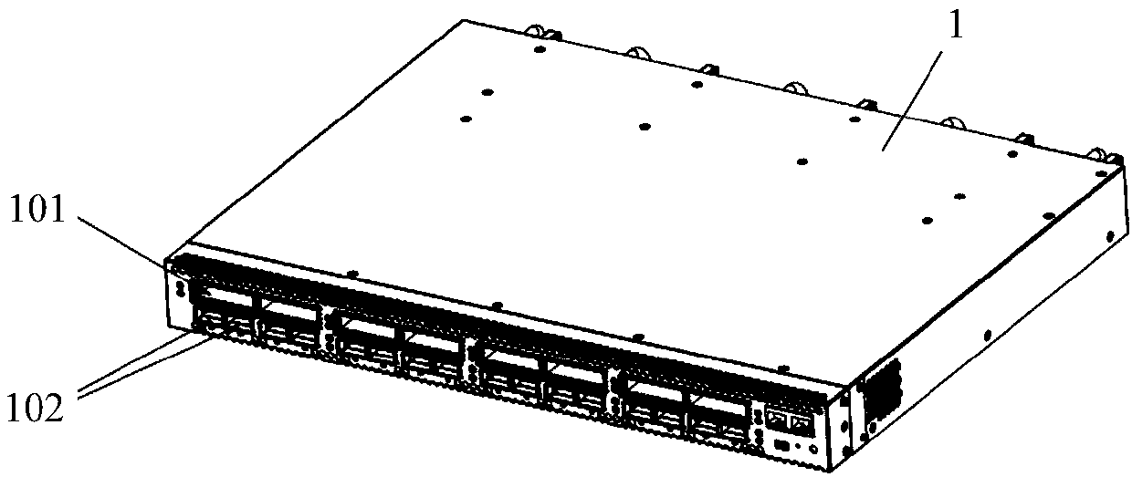
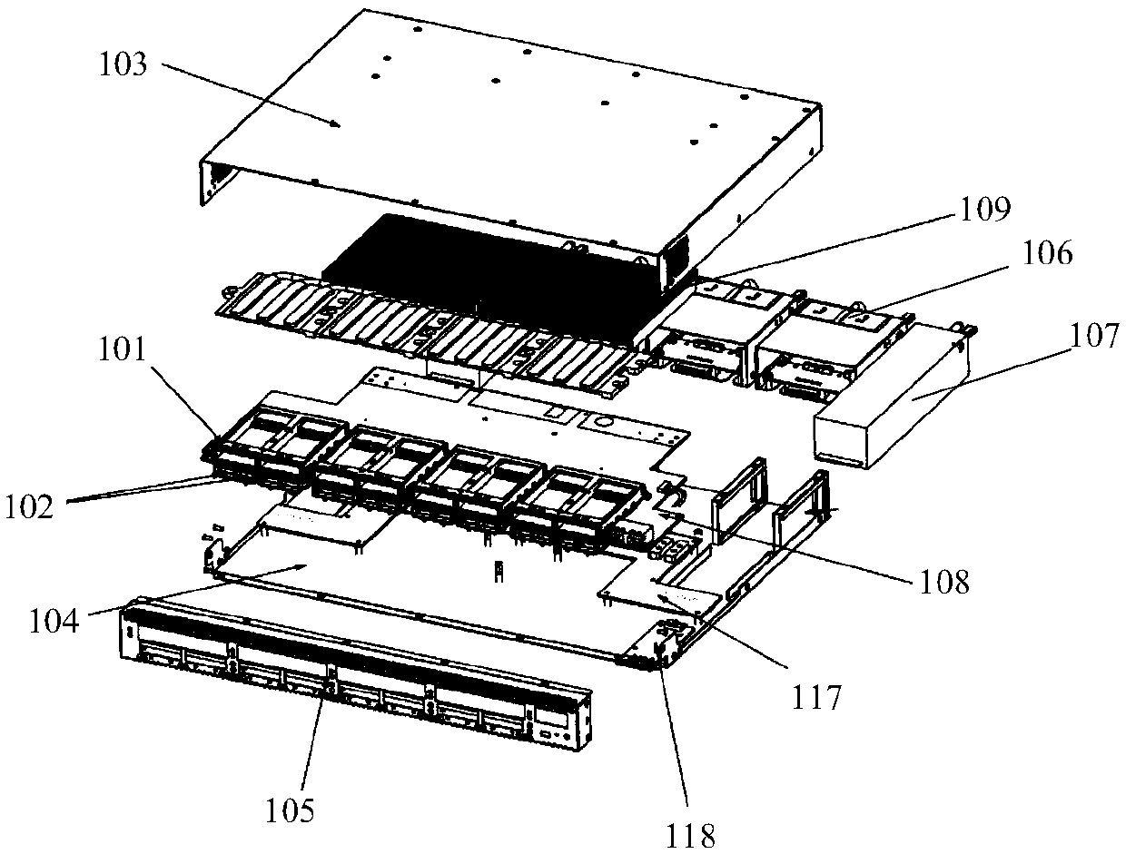
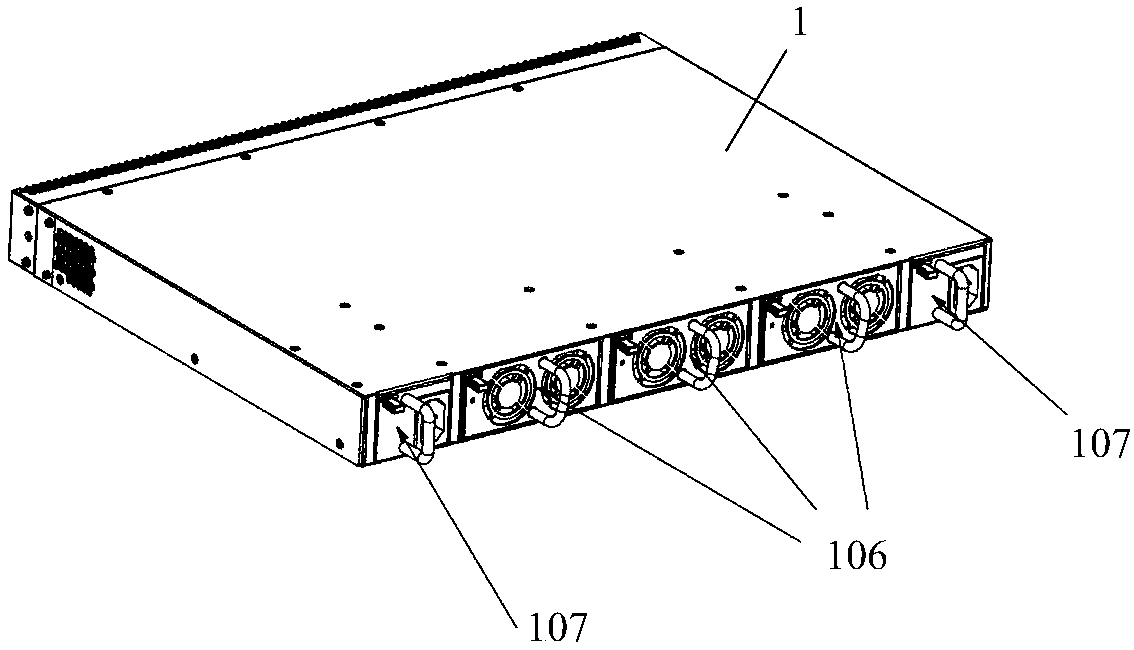
[0028] This application is about the design of optical transmission equipment, especially related to multi-service optical transmission platform equipment. This type of optical transmission platform equipment can be inserted with multiple optical modules to achieve multiple services. Optical modu...


PUM


Abstract

The application provides optical transmission equipment comprising at least one optical module cage unit fixedly arranged on a service circuit board. The optical module cage unit comprises one or morefirst optical module cages arranged on the upper layer and one or more second optical module cages arranged on the lower layer. Each first optical module cage is used for placing one or more first optical modules, and each second optical module cage is used for placing a second optical module; the first optical module is used for service side optical communication connection, and the second optical module is used for client side optical communication connection. Welding pins of the first optical module cage and the second optical module cage are staggered and do not interfere with each other.The optical module cages on the service side and the sending side are stacked and do not interfere with each other, so that more spare space in the equipment is provided for configuring more opticalmodules and thus the interface density is improved; and heat dissipation of the first optical module on the service side with relatively high power consumption is facilitated.

Description

technical field [0001] The present application relates to the technical field of optical transmission network, in particular to optical transmission equipment. Background technique [0002] At present, the common optical transmission equipment supporting CFP2 includes the blade plug-in type of large chassis and the standard 1U chassis type. [0003] Blade plug-in card type in a large chassis: The whole machine is large and has complete functions. Although it can support different business communication functions, the disadvantage is that the height of this kind of equipment is above 12U (540mm), and the power consumption of the equipment is 2000 watts. above. This kind of equipment is suitable for use in a large-scale overall project plan, which requires sufficient planning for the cabinet space and power distribution and energy consumption of the entire project. However, in the general single business demand, it will cause necessary cost increases. In addition, it cannot ...

Claims


Application Information

Patent Timeline
IPC IPC(8): G02B6/42G02B6/43
CPCG02B6/4268G02B6/43
Inventor 徐文明时书敏马苗苗陈孝勇吴攀峰周亮肖鸿谢虎吴志远李琳
Owner SHANGHAI SINO TELECOM TECH
Why Eureka
Try Eureka