Optical filter, fingerprint detection device and electronic device

A fingerprint detection and optical filter technology, applied in the field of biometric identification, can solve the problems affecting the performance of fingerprint detection, the interference of optical fingerprint detection under the screen, etc.

Active Publication Date: 2020-04-24
SHENZHEN GOODIX TECH CO LTD
View PDF8 Cites 1 Cited by
  • Summary
  • Abstract
  • Description
  • Claims
  • Application Information

AI Technical Summary

Problems solved by technology

However, when performing fingerprint detection, light in non-target bands such as red light and infrared light will interfere with off-screen optical fingerprint detection
For example, when performing fingerprint detection outdoors, the red light and infrared light in the sunlight can directly pass through the finger to reach the optical fingerprint module, so that the light carrying the fingerprint signal is lost in the background noise of the red light and infrared light, which affects the Performance of fingerprint detection under optical screen

Method used


Image

  • Optical filter, fingerprint detection device and electronic device
  • Optical filter, fingerprint detection device and electronic device
  • Optical filter, fingerprint detection device and electronic device

Examples


Embodiment Construction

[0046] The technical solution in this application will be described below with reference to the accompanying drawings.

[0047] It should be understood that the embodiments of the present application can be applied to fingerprint systems, including but not limited to optical, ultrasonic or other fingerprint recognition systems and medical diagnostic products based on optical, ultrasonic or other fingerprint imaging. The embodiments of the present application only take the optical fingerprint system as an example description, but should not constitute any limitation to the embodiment of the present application, and the embodiment of the present application is also applicable to other systems using optical, ultrasonic or other imaging technologies.

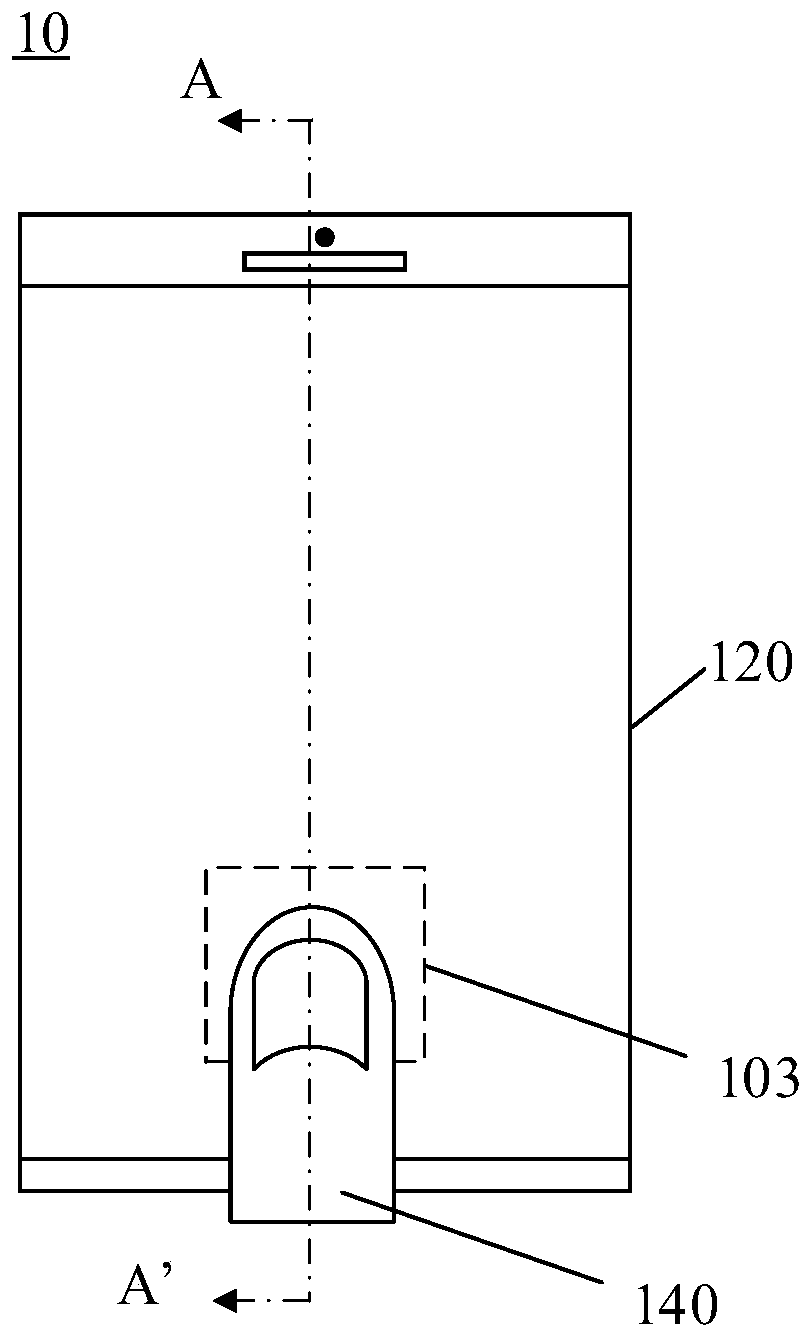
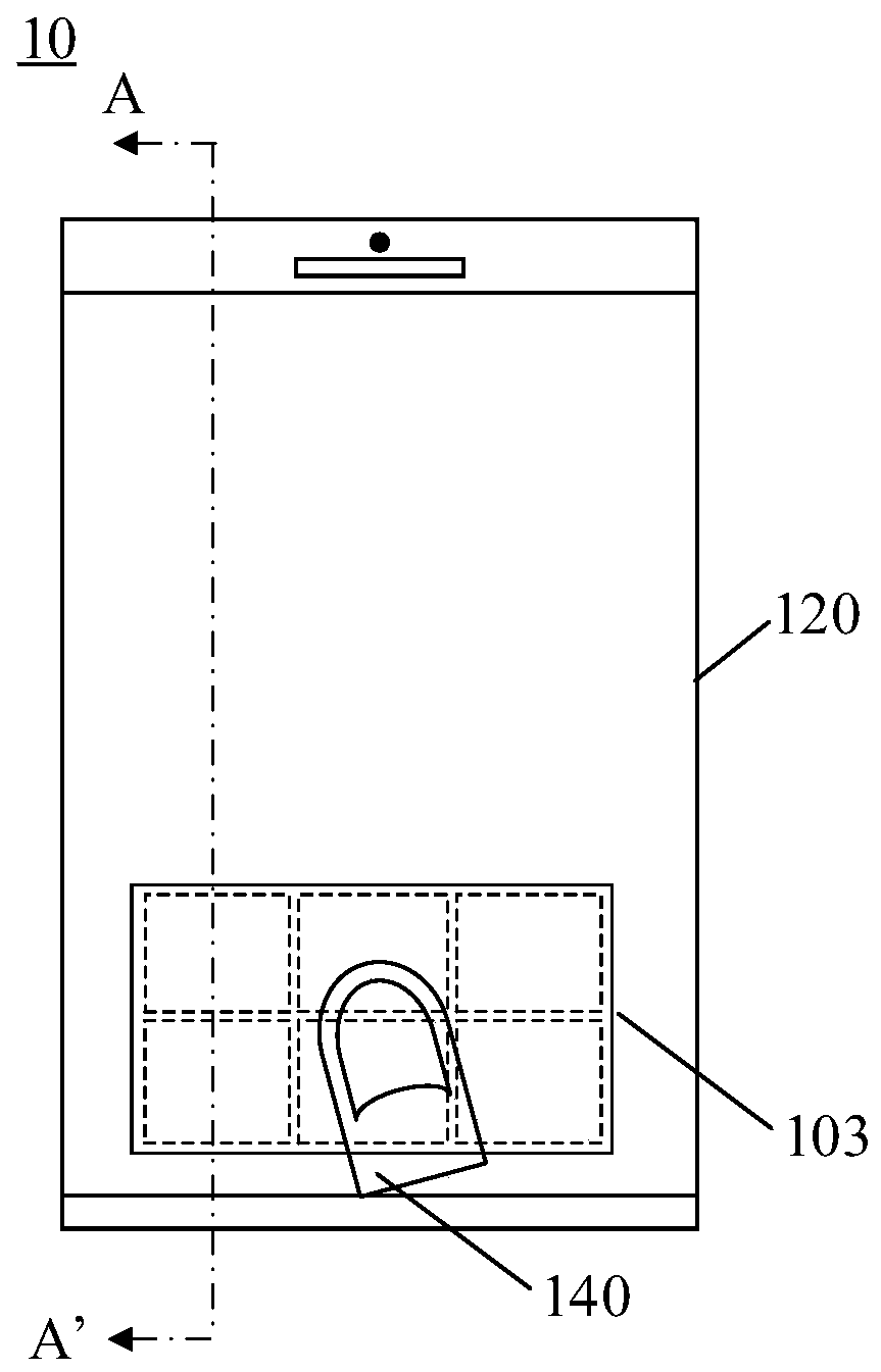
[0048] As a common application scenario, the optical fingerprint system provided by the embodiment of this application can be applied to smart phones, tablet computers, and other mobile terminals with display screens or other electro...


PUM

PropertyMeasurementUnit
wavelengthaaaaaaaaaa
thicknessaaaaaaaaaa

Abstract

The invention provides an optical filter, which does not influence the visual perception of a user while ensuring the fingerprint detection performance, and has good structural stability. The opticalfilter is arranged between the display screen and the optical fingerprint sensor. The optical fingerprint sensor is used for detecting an optical signal returned by a finger above the display screen.The optical filter is used for filtering an optical signal of a non-target waveband in an optical path of the optical fingerprint sensor, the optical signal of the non-target waveband comprises an optical signal of a red light waveband and an optical signal of an infrared waveband, and the optical filter comprises a substrate; at least one cut-off film layer, used for reflecting the optical signals of the non-target waveband, and the at least one cut-off film layer is located on the two sides of the substrate; and at least one coating, used for absorbing the optical signal of the non-target waveband.

Description

technical field [0001] The embodiment of the present application relates to the field of biometric identification, and more specifically, relates to an optical filter, a device for detecting fingerprints, and an electronic device. Background technique [0002] The optical fingerprint module collects light reflected or transmitted on the finger and returns it, and realizes fingerprint recognition under the optical screen according to the fingerprint information of the finger carried in the light. However, when fingerprint detection is performed, light in non-target bands such as red light and infrared light will interfere with off-screen optical fingerprint detection. For example, when performing fingerprint detection outdoors, the red light and infrared light in the sunlight can directly pass through the finger to reach the optical fingerprint module, so that the light carrying the fingerprint signal is lost in the background noise of the red light and infrared light, which ...

Claims


Application Information

Patent Timeline
Patent Type & Authority Applications(China)
IPC IPC(8): G06K9/00G06K9/20
CPCG06V40/1324G06V10/143G06V10/147
Inventor 高攀吴宝全刘辰锦
Owner SHENZHEN GOODIX TECH CO LTD
Why Eureka
Try Eureka