
Multi-rotor-wing unmanned aerial vehicle having centrifugal nozzles

A multi-rotor unmanned aerial vehicle and centrifugal technology, which is applied to rotorcraft, unmanned aircraft, motor vehicles, etc., can solve problems such as difficult to provide, weak spraying strength, and difficult research, so as to improve spraying effect and improve The effect of power output and improvement of usability

Active Publication Date: 2020-04-28
广东利顺科技有限公司
View PDF10 Cites 3 Cited by
  • Summary
  • Abstract
  • Description
  • Claims
  • Application Information

AI Technical Summary

Problems solved by technology

But for multi-rotor drones, since the motor of the propeller is mainly used to provide power for the propeller, and the impeller in the nozzle is only used as a linkage to provide power output, although under the rotation of the impeller, the spray liquid can be dispersed. To achieve the atomization effect, but it is difficult to provide enough power to output the spray liquid, resulting in weak spray liquid intensity, unable to penetrate the interior of the crops, and difficult to meet the spraying requirements
[0006] Therefore, the UAVs of the prior art cannot meet the requirements of hovering spraying and spraying intensity at the same time, which is a research problem for current agricultural UAV manufacturers.

Method used


Image

  • Multi-rotor-wing unmanned aerial vehicle having centrifugal nozzles
  • Multi-rotor-wing unmanned aerial vehicle having centrifugal nozzles
  • Multi-rotor-wing unmanned aerial vehicle having centrifugal nozzles

Examples


Embodiment Construction

[0048] Embodiments of the present invention are described in detail below, examples of which are shown in the drawings, wherein the same or similar reference numerals designate the same or similar elements or elements having the same or similar functions throughout. The embodiments described below by referring to the figures are exemplary and are intended to explain the present invention and should not be construed as limiting the present invention.

[0049] In describing the present invention, it should be understood that the terms "length", "width", "upper", "lower", "front", "rear", "left", "right", "vertical", The orientation or positional relationship indicated by "horizontal", "top", "bottom", "inner", "outer", etc. are based on the orientation or positional relationship shown in the drawings, and are only for the convenience of describing the present invention and simplifying the description, rather than Nothing indicating or implying that a referenced device or element...


PUM


Abstract

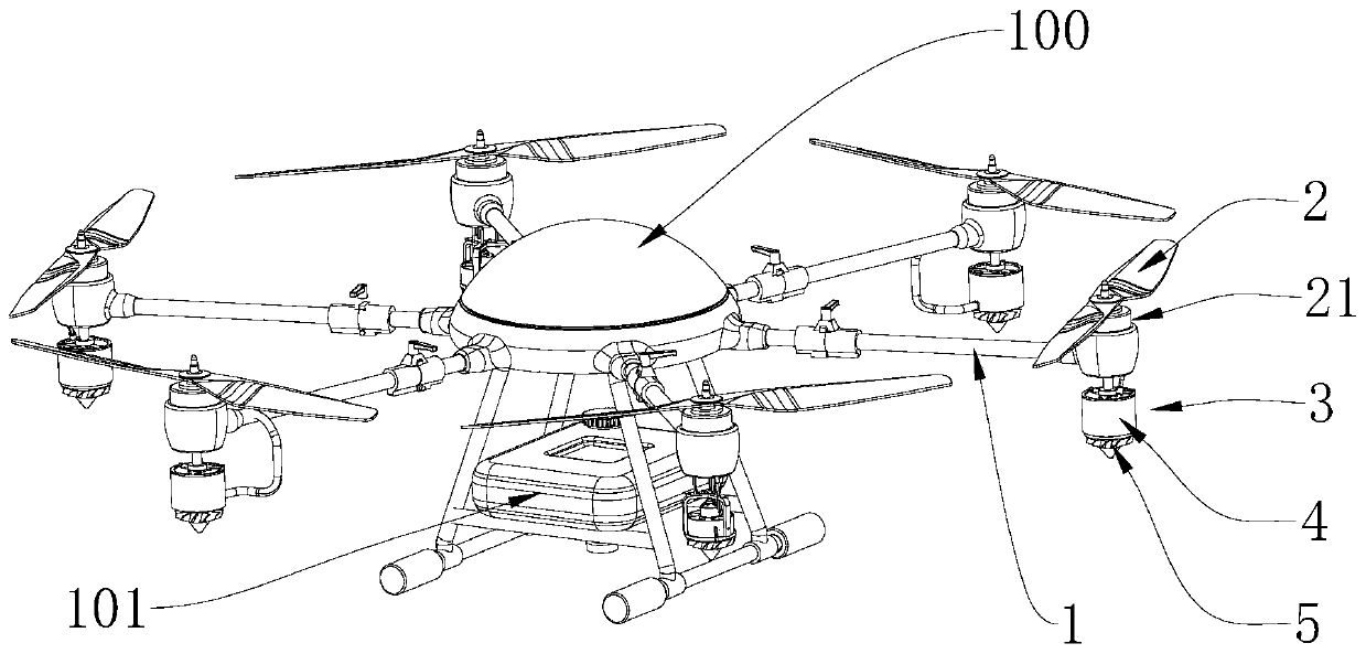
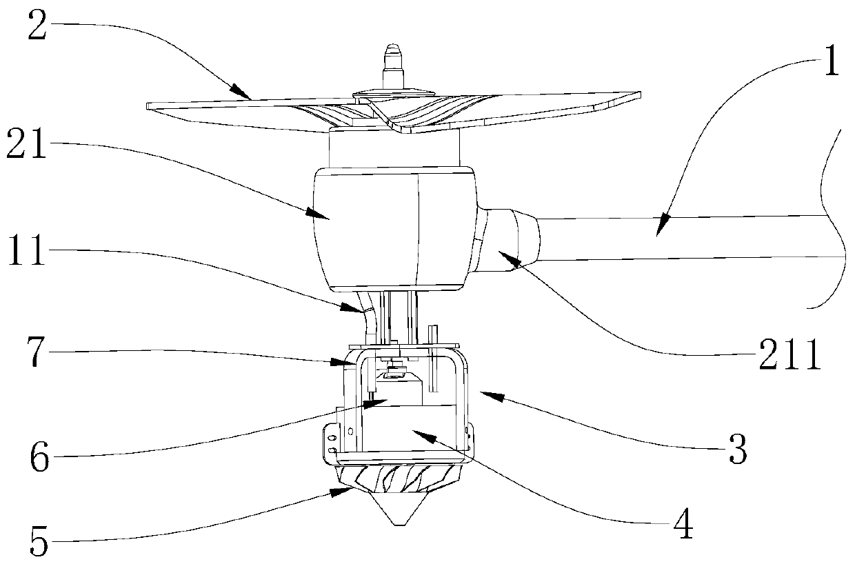
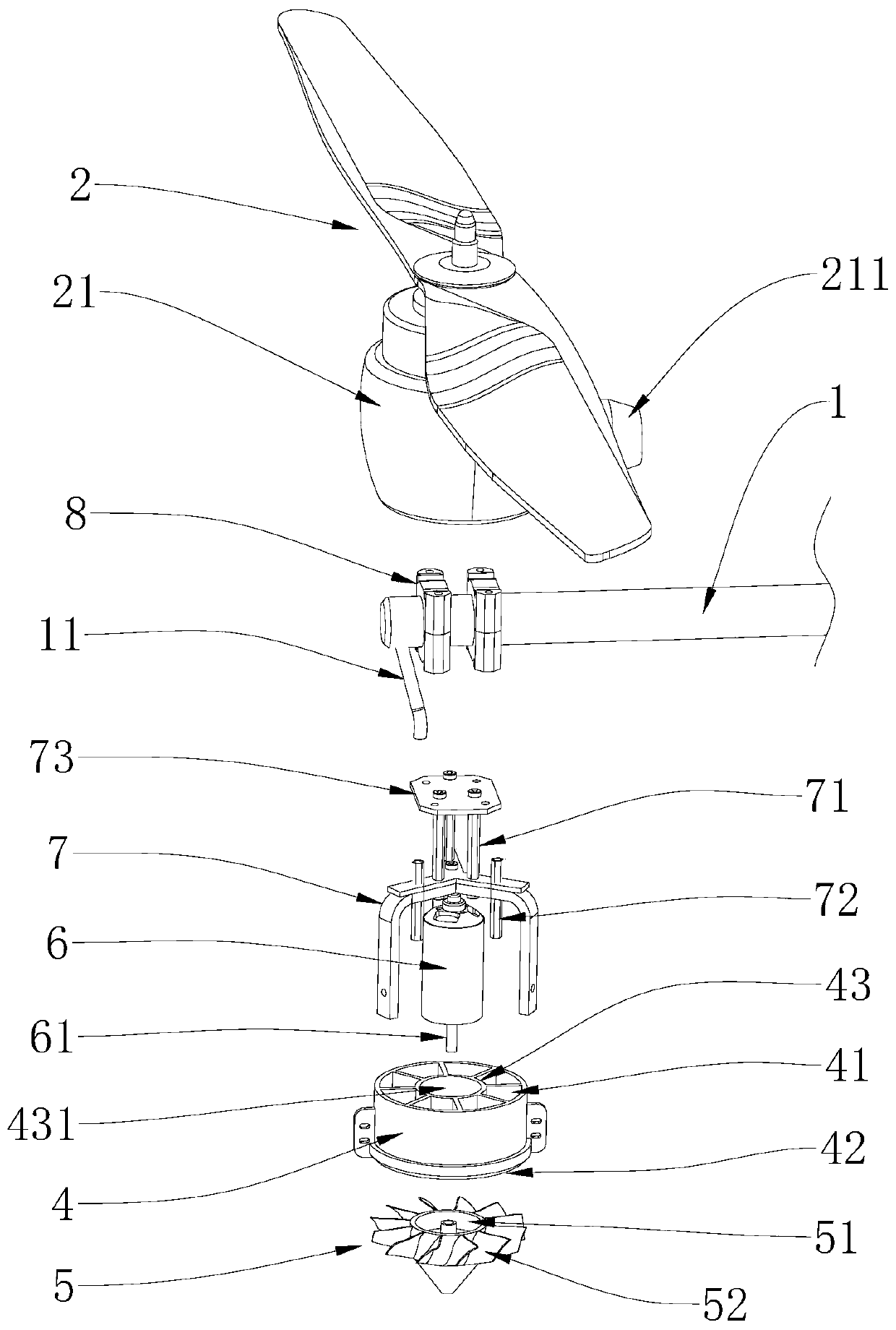
The invention relates to the technical field of agricultural unmanned aerial vehicles, and provides a multi-rotor-wing unmanned aerial vehicle having centrifugal nozzles. The multi-rotor-wing unmannedaerial vehicle comprises a fuselage and a plurality of hollow wing arms, wherein the fuselage is provided with a container, and the multiple hollow wing arms are connected with the fuselage; each wing arm is provided with a driving seat; each driving seat is provided with a propeller; each wing arm is further provided with the corresponding nozzle; each nozzle includes a flow guide sleeve, an impeller and a motor; each motor is fixed into the corresponding flow guide sleeve; each motor is provided with a driving shaft; each driving shaft extends to the outside of the corresponding flow guidesleeve from the corresponding motor; each impeller is arranged on the outside of an opening of the corresponding flow guide sleeve, and is connected with the driving shaft of the corresponding motor;a liquid conveying pipe is arranged in each wing arm; and one end of each liquid conveying pipe is connected with the container on the fuselage, and the other end of each liquid conveying pipe is connected with the corresponding flow guide sleeve. According to the multi-rotor-wing unmanned aerial vehicle, nozzle structures of the unmanned aerial vehicle are improved, and thus, while sprayed liquidis atomized effectively, the strength of the sprayed liquid can be enhanced, so that sprayed liquid can penetrate interiors of crops, and the spraying effect is effectively improved.

Description

technical field [0001] The invention relates to the technical field of agricultural drones, in particular to a multi-rotor drone with a centrifugal nozzle. Background technique [0002] UAV is an unmanned aircraft operated by radio remote control equipment and self-contained program control device. With the rapid development of science and technology, drone technology is becoming more and more mature, and the application of drones has gradually entered the public eye, and the application of drones in civilian applications is becoming more and more extensive, especially in planting. UAVs can effectively replace manual operations by spraying pesticides or fertilizing crops, saving operating time and labor costs, and improving production efficiency. [0003] At present, agricultural drones on the market are generally divided into two types, including drones with fixed wings and drones with multi-rotors. For fixed-wing unmanned aerial vehicles, since a certain distance and spa...

Claims


Application Information

Patent Timeline
Patent Type & Authority Applications(China)
IPC IPC(8): A01M7/00B64D1/18B64C27/08
CPCA01M7/0025B64D1/18B64C27/08B64U10/10B64U2101/00
Inventor 林壮练杨明东
Owner 广东利顺科技有限公司
Learn More