Cleaning device for optical lens production and machining
A technology for optical lenses and cleaning devices, which is applied in the direction of using liquid cleaning methods, cleaning flexible objects, and drying gas arrangement, etc. It can solve the problems of cleaning effect that needs to be improved, cleaning is not thorough, etc., and achieves the effect of thorough cleaning and improved cleaning effect
- Summary
- Abstract
- Description
- Claims
- Application Information
AI Technical Summary
Problems solved by technology
Method used
Image


Examples
Embodiment 1
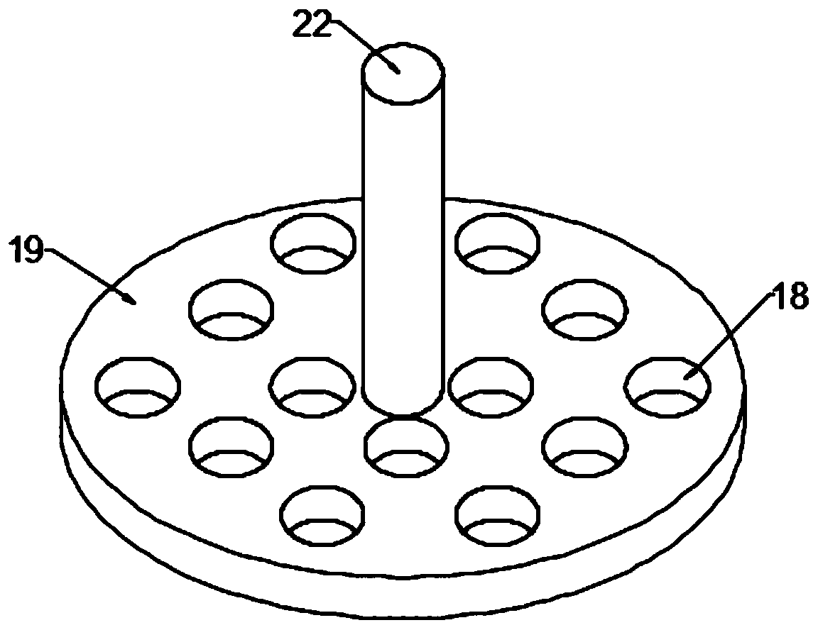
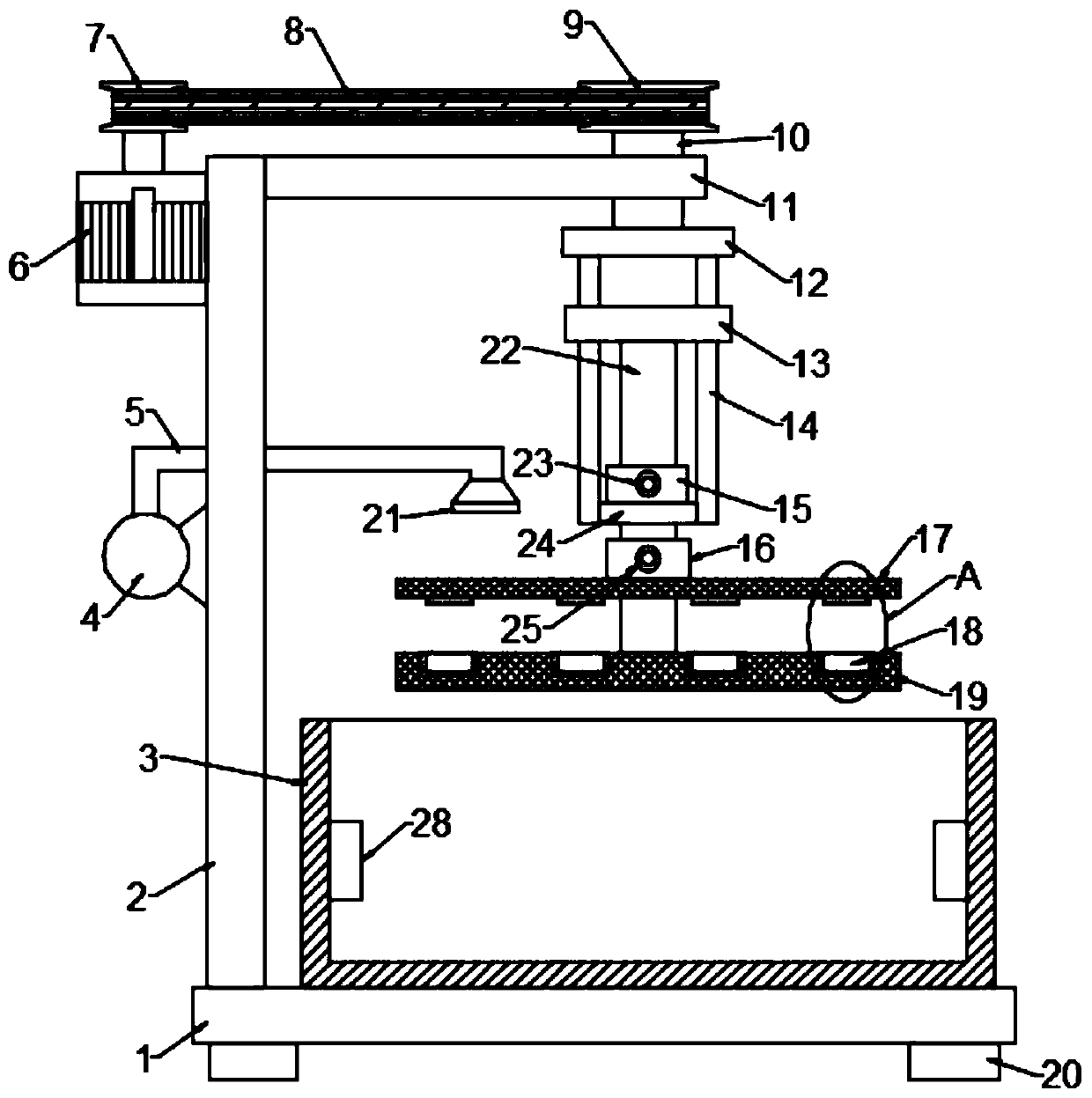
[0027] see Figure 1-2 , in an embodiment of the present invention, a cleaning device for optical lens production and processing includes a supporting base plate 1, a cleaning tank 3 is provided on the supporting base plate 1, and a foot 20 is provided at the bottom of the supporting base plate 1; A column 2 is fixed on the bottom plate 1, a support plate 11 is fixed on the top of the column 2, and a grid cover 17 and a grid support plate 19 are provided on the underside of the support plate 11. A plurality of lens grooves 18 distributed in an array, a slide bar 22 is connected to the center of the grid support plate 19, and the grid cover 17 is slidably arranged on the slide bar 22;
[0028] An ultrasonic generator 28 is installed in the cleaning tank 3, and the cleaning device for optical lens production and processing also includes an adjustment assembly for adjusting the height of the grid support plate 19 and a drive assembly for driving the grid support plate 19 to rotat...
Embodiment 2
[0039] see Figure 3-4 , in the embodiment of the present invention, a cleaning device for optical lens production and processing is different from embodiment 1 in that an upper protective pad 26 is provided on the bottom surface of the grid cover 17 corresponding to the lens groove 18, and the lens The inner wall of the groove 18 is provided with a lower protective pad 27; the optical lens is placed in the lens groove 18, and the optical lens can be effectively protected by using the upper protective pad 26 and the lower protective pad 27 to avoid the optical lens from contacting the grid supporting plate 19 and the grid. Gland 17 contacts, damages the surface.
PUM
 Abstract
Description
Claims
Application Information
 - Generate Ideas
- Intellectual Property
- Life Sciences
- Materials
- Tech Scout
- Unparalleled Data Quality
- Higher Quality Content
- 60% Fewer Hallucinations
Browse by: Latest US Patents, China's latest patents, Technical Efficacy Thesaurus, Application Domain, Technology Topic, Popular Technical Reports.
© 2025 PatSnap. All rights reserved.Legal|Privacy policy|Modern Slavery Act Transparency Statement|Sitemap|About US| Contact US: help@patsnap.com