Guide Mechanism for Fillet Punching Die
A guiding mechanism and punching technology, which is applied in the field of auto parts manufacturing, can solve the problems that the guiding mechanism cannot obtain sufficient lubricating fluid, unfavorable normal operation of the guiding mechanism, and large internal friction, so as to facilitate normal operation, avoid failure to lubricate, and reduce The effect of high internal friction
- Summary
- Abstract
- Description
- Claims
- Application Information
AI Technical Summary
Problems solved by technology
Method used
Image

Examples
Embodiment 1
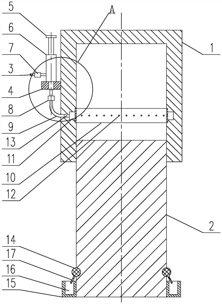
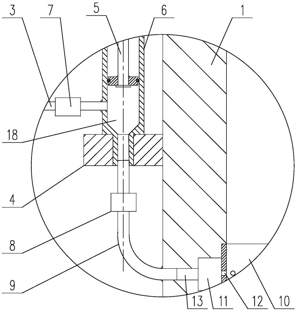
[0030] Such as figure 1 and figure 2 As shown, a guiding mechanism for a fillet punching die of the present invention includes a guide sleeve 1 connected to an upper die base and a guide post 2 connected to a lower die base, and the top end of the guide post 2 is inserted into the guide sleeve 1 In the inner hole, a lubricating pipe 3 is arranged on the guide sleeve 1, the feed end of the lubricating pipe 3 communicates with the lubricating liquid source, and its discharge end communicates with the inner hole of the guide sleeve 1, and the lubricating pipe 3 The discharge end communicates with the inner hole of the guide sleeve 1 through a lubricating assembly; the lubricating assembly includes a piston rod 5, a cylinder 6, a first one-way valve 7, a second one-way valve 8, a connecting pipe 9 and a damping ring 10 ,in,
[0031] On the outer wall of the guide sleeve 1, a support plate 4 is connected, and a threaded through hole is provided on the support plate 4; on the inn...
Embodiment 2
[0039] This embodiment is based on Embodiment 1 to further illustrate the implementation of the present invention.
[0040] In actual use, the more lubricating fluid, the more conducive to the lubrication and heat dissipation of the guide column 2 and the guide sleeve 1 . If there is too much lubricating fluid between the guide post and the guide sleeve, it will flow down the guide post to the lower die base under the action of gravity, causing the entire lower die base to be contaminated with lubricating liquid and dust. Therefore, in the present invention, a collection assembly is provided on the side of the guide post 2 away from the guide sleeve 1, and the collection assembly includes a rubber sealing ring 14 and a collection ring 15 whose axes all coincide with the axis of the guide post 2. The collection ring 15 is sleeved on the guide column 2, and is threadedly connected with the side wall of the guide column 2 close to the lower mold seat, and an annular collection gr...
Embodiment 3
[0048] This embodiment is based on the embodiment 1, and is further described for the implementation of the invention.
[0049] In the present invention, the cylinder body 6 is made of a transparent material, and a scale line for marking the height dimension of the accommodating cavity is provided on its side wall along its axis.
[0050] The cylinder body 6 is made of a transparent material, which is convenient for further accurately knowing the amount of lubricating liquid obtained by each mold.
[0051] Since the outer diameter of the damping ring 10 is larger than the inner diameter of the guide cylinder, in order to facilitate the installation of the damping ring 10, the following methods can be adopted.
[0052] Method 1, the guide cylinder is divided into left half cylinder and right half cylinder equally by the plane passing its axis. A sealing ring is provided at the matching part with the installation groove, which is used to improve the sealing performance of the m...
PUM
 Abstract
Description
Claims
Application Information
 - R&D Engineer
- R&D Manager
- IP Professional
- Industry Leading Data Capabilities
- Powerful AI technology
- Patent DNA Extraction
Browse by: Latest US Patents, China's latest patents, Technical Efficacy Thesaurus, Application Domain, Technology Topic.
© 2024 PatSnap. All rights reserved.Legal|Privacy policy|Modern Slavery Act Transparency Statement|Sitemap