
A coating line automatic transfer machine equipment

A transfer machine and coating line technology, applied in spraying devices, conveyor objects, transportation and packaging, etc., can solve the problems of large space occupation, low flexibility, and influence on production progress, so as to reduce floor space and increase Flexibility and the effect of improving productivity

Active Publication Date: 2021-05-04
东莞市慧江平成机械有限公司
View PDF6 Cites 0 Cited by
  • Summary
  • Abstract
  • Description
  • Claims
  • Application Information

AI Technical Summary

Problems solved by technology

[0002] The transfer machine is generally used for the transfer and transportation of items, and is suitable for various production lines. In the coating industry, the hanging transfer machine is generally used to transfer the required coating products, and the coating process includes electrophoretic coating , coating sealant, spraying paint, inspection and other multi-channel processes, multi-channel processes need to be carried out in different workshop production lines, and using the existing hanging type transfer machine, it is necessary to connect the track layout of the transfer machine to multiple workshops , takes up a lot of space and is less flexible. The existing solution is to design multiple tracks, but each track needs manual cooperation when reloading. Manually use hoists and hoisting equipment for reloading. The two production lines are suspended at the same time, the efficiency of manual transfer is slow, and the suspension will affect the production progress. Therefore, the applicant has developed an automatic transfer machine equipment for coating lines that can realize automatic transfer to solve the above problems

Method used


Image

  • A coating line automatic transfer machine equipment
  • A coating line automatic transfer machine equipment
  • A coating line automatic transfer machine equipment

Examples


Embodiment Construction

[0024]In order to make the above objects, features, and advantages of the present invention, the specific embodiments of the present invention will be described in detail below with reference to the accompanying drawings. It is to be noted that the appended claims Non-accurate comparisons are used in the accompanying forms of the present invention.

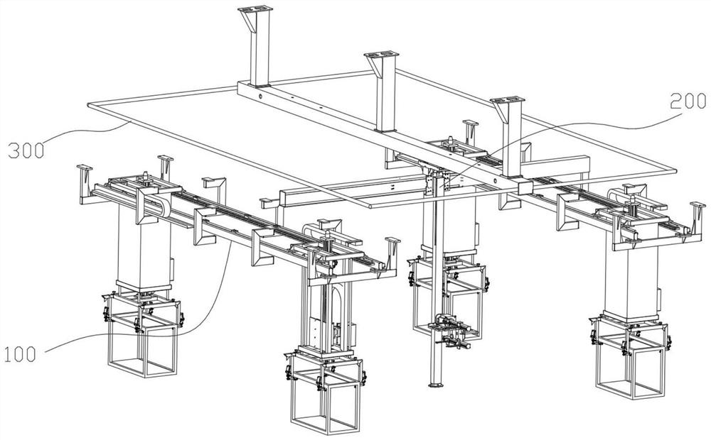
[0025]Such asFigure 1 ~ 5As shown, a coating line automatic transfer machine, including a lifting shift line 100, a drift transfer line 200, a follow-up positioning system 300;

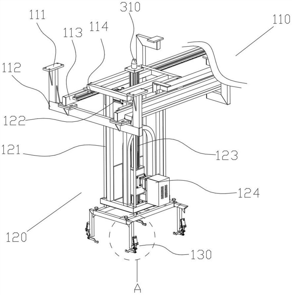
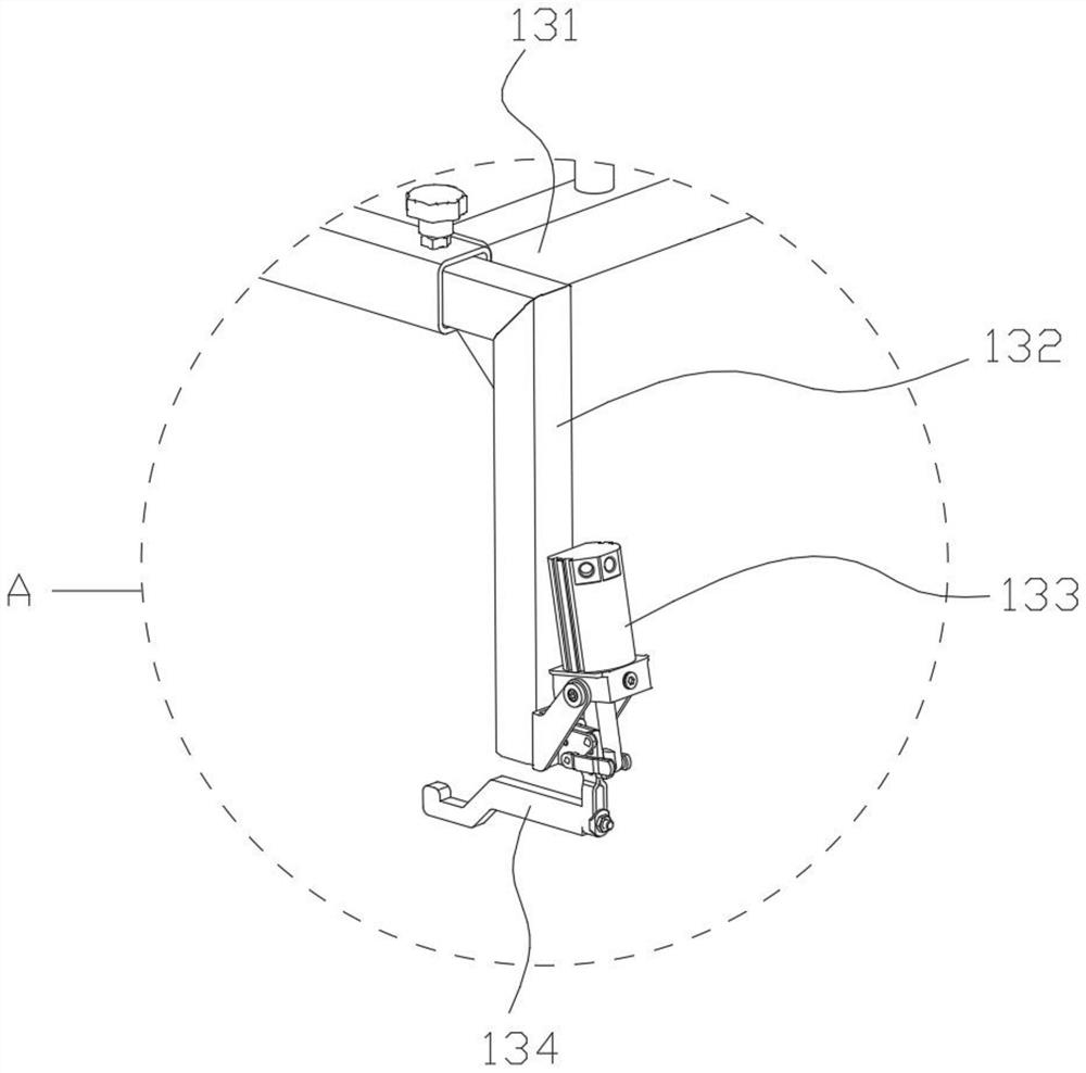
[0026]In the present embodiment, the lifting shift line 100 is provided with two groups and is used in different production lines, including a lifting-filled trace 110, and several slides connected to the lifting transfer slide rail 110. The lifting transfer assembly 120; the lifting shift rail 110 includes several first ceramics 31, a plurality of cross-frame 112, a lifting transfer rail 113, a stroke rack 114; the cross-frame 112 is fixed to a fixed pitch Parallel ...


PUM


Abstract

The invention discloses an automatic transfer machine equipment for a coating line, which includes a lifting transfer line, a transfer transfer line, and a follow-up positioning system; the lifting transfer line is provided with two groups, which are used in different production lines Among them, it includes lifting and transferring slide rails and lifting and transferring components; the transfer and transfer line is arranged between the lifting and transferring lines, and is used to transfer the products on one group of lifting and transferring lines to another group, which includes Reload transfer slide rails, transfer mount transfer components; the follow-up positioning system includes signal sending components and signal receiving components; It is within the acceptance range of the signal receiving element, and is electrically connected with the transfer load transfer line, which is used to synchronize the travel of the transfer transfer assembly and the lifting transfer assembly to realize follow-up positioning, which has the advantages of improving production efficiency, increasing flexibility, reducing The advantages of occupying an area and helping the transfer machine to realize modular combination.

Description

Technical field[0001]The present invention relates to the technical field of transfer unit, and more particularly to a coating wire automatic transfer device.Background technique[0002]The transfer machine is generally used for the transfer and transport of the item. It is suitable for use in various production lines, and the coating industry is generally transferred to the desired coating product, while the coating process includes electrophoresis painting. , Coated sealing, spray paint, inspection and other multi-channel processes, multi-channel processes need to be carried out in different workshop production lines, while using existing hanging loaders, the transfer machine track is required to connect multiple workshops. The occupancy is large, the existing solution is designed to design multiple tracks, but there is a manual cooperation between each track, manual use of hoist and hungry equipment, and it needs to be reprinted The two production lines are simultaneously suspended...

Claims


Application Information

Patent Timeline
Patent Type & Authority Patents(China)
IPC IPC(8): B65G47/90B05B13/02
CPCB05B13/0221B65G47/901B65G47/905
Inventor 罗佳孙泽江于小勇吕少怀
Owner 东莞市慧江平成机械有限公司
Learn More