
A tunnel decompression device

A decompression and tunnel technology, applied in tunnels, mining installations, mining equipment, etc., to solve problems such as passenger discomfort, temporary tinnitus, etc.

Inactive Publication Date: 2021-07-30
南京溧水高新产业股权投资有限公司
View PDF6 Cites 0 Cited by
  • Summary
  • Abstract
  • Description
  • Claims
  • Application Information

AI Technical Summary

Problems solved by technology

[0003] But now when the train enters the tunnel, due to the instantaneous compression of the air, temporary tinnitus often occurs, which makes many passengers feel unwell

Method used


Image

  • A tunnel decompression device
  • A tunnel decompression device
  • A tunnel decompression device

Examples


Embodiment Construction

[0016] The following will clearly and completely describe the technical solutions in the embodiments of the present invention with reference to the accompanying drawings in the embodiments of the present invention. Obviously, the described embodiments are only some, not all, embodiments of the present invention.

[0017] In describing the present invention, it is to be understood that the terms "center", "longitudinal", "transverse", "length", "width", "thickness", "upper", "lower", "front", " Orientation or position indicated by "back", "left", "right", "vertical", "horizontal", "top", "bottom", "inner", "outer", "clockwise", "counterclockwise", etc. The relationship is based on the orientation or positional relationship shown in the drawings, and is only for the convenience of describing the present invention and simplifying the description, rather than indicating or implying that the referred device or element must have a specific orientation, be constructed and operated in ...


PUM


Abstract

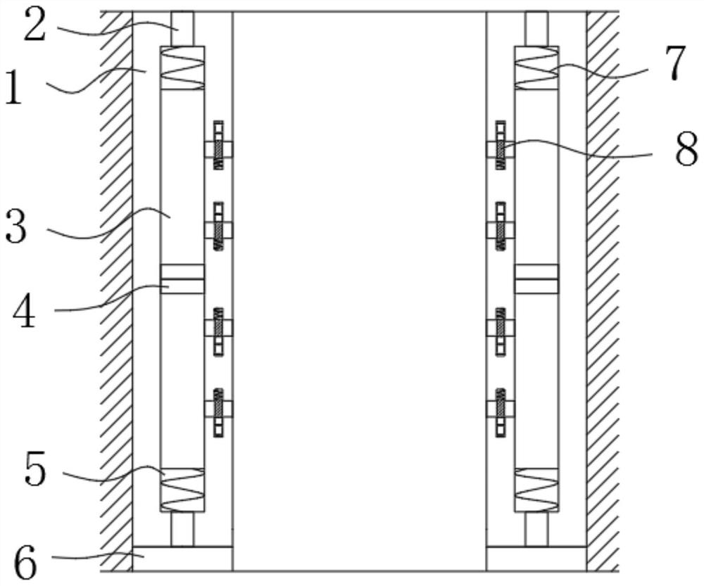
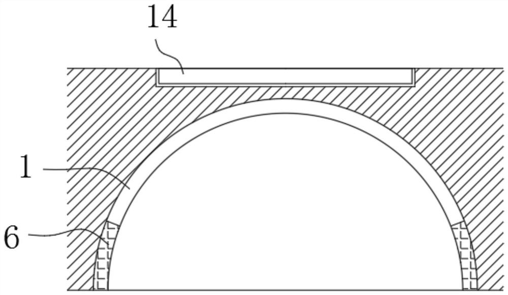
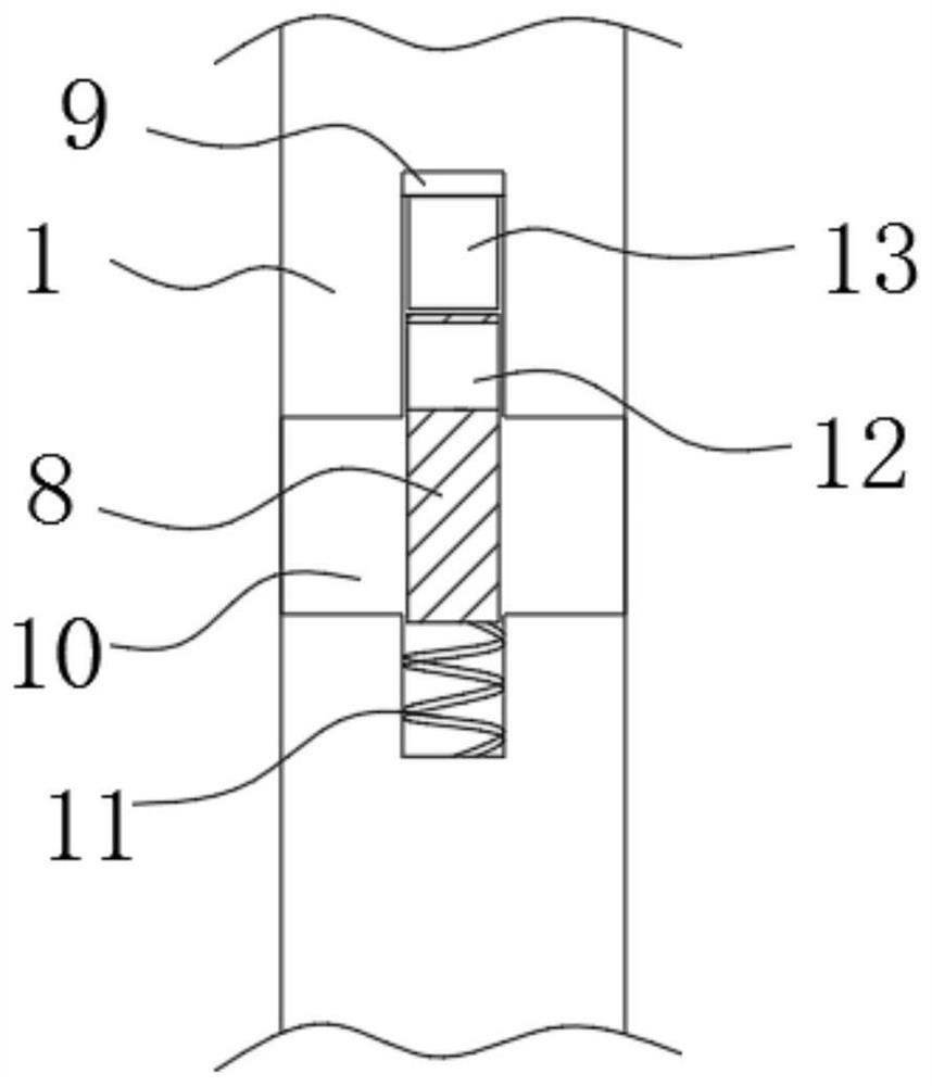
The invention discloses a tunnel depressurization device, which comprises an assembly plate installed in the tunnel, a suction cavity arranged longitudinally is opened in the assembly plate, and two ends of the suction cavity are provided with interconnecting holes for communicating with the outside world. Ventilation duct, the inside of both ends of the suction chamber is fixedly connected with a magnet column, the middle of the magnet column is provided with an aperture communicating with the ventilation duct, the magnet column is also wound with an excitation coil, and the suction cavity is symmetrical A magnet plate is slidably connected, and a plurality of air vents are arranged at equal intervals on the assembly plate, and a first installation slot and a second installation slot are respectively provided on both sides of each of the air vents. In the present invention, through the interaction of the suction chamber, magnet plate, magnet column, excitation coil, heating plate and other structures, most of the extruded air enters the suction chamber, resulting in increased space for compressed air and reduced pressure. , so as to avoid tinnitus in the tunnel.

Description

technical field [0001] The invention relates to the technical field of civil engineering, in particular to a tunnel decompression device. Background technique [0002] Civil engineering is a general term for the science and technology of building various engineering facilities. It not only refers to the applied materials, equipment and technical activities such as survey, design, construction, maintenance and repair; , production, military, and various engineering facilities for scientific research services. [0003] But now when the train enters the tunnel, due to the instantaneous compression of the air, temporary tinnitus often occurs, which makes many passengers feel uncomfortable. Contents of the invention [0004] The purpose of the present invention is to solve the following shortcomings in the prior art. Now when the train enters the tunnel, because the air is compressed instantaneously, the phenomenon of temporary tinnitus often occurs, which makes many passenge...

Claims


Application Information

Patent Timeline
Patent Type & Authority Patents(China)
IPC IPC(8): E21D9/14E21F17/00
CPCE21D9/14E21F17/00
Inventor 赵龙飞蔡路
Owner 南京溧水高新产业股权投资有限公司
Learn More