Fixing frame for thermocouple
A fixed frame and thermocouple technology, applied in measuring heat, using directly heat-sensitive electrical/magnetic element thermometers, using electrical devices, etc., can solve the problems of cumbersome position adjustment operations, thermocouple loss, and insufficient fixation, etc. , to achieve the effect of firm assembly, reduced friction and high practicability
- Summary
- Abstract
- Description
- Claims
- Application Information
AI Technical Summary
Problems solved by technology
Method used
Image

Examples
Embodiment 1
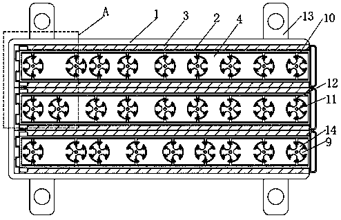
[0020] A fixing frame for thermocouples, comprising a main frame body 1, a built-in frame plate 4, fixing ears 13 and a circular frame plate 14, the outer surface of the main frame body 1 is welded with fixing ears 13, and the inside of the main frame body 1 is provided with There is a fixed notch 2, and a built-in frame plate 4 is inserted horizontally inside the fixed notch 2, and mounting blocks 5 are welded on both sides of one end of the built-in frame plate 4, and there are mounting blocks on both sides of the inner wall of the fixed notch 2. 5 The installation groove 3 that cooperates with each other, the inner wall surface of the built-in shelf plate 4 is provided with an adjustment groove 10, and the inside of the adjustment groove 10 is embedded with an adjustment block 12, and the surface of the adjustment block 12 away from the adjustment groove 10 is welded with a circular frame plate 14, and the surface of the circular frame plate 14 is provided with fixing compon...
Embodiment 2
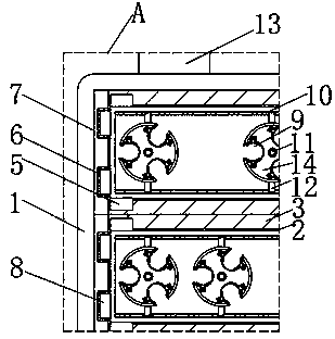
[0022] One side of the inner wall of the fixed notch 2 is welded with a receiving plate 7, and the surface of the receiving plate 7 is provided with a card slot 6, and one end of the built-in shelf plate 4 is welded with a card block 8 that cooperates with the card slot 6, and the card slot 6 and Block 8 constitutes a snap-fit structure, according to the attached figure 1 And attached figure 2 As shown, before use, through the horizontal sliding of the installation block 5 in the installation groove 3, and the engagement of the card slot 6 and the card block 8, the user aligns one side of the built-in shelf plate 4 and inserts it into the fixing slot 2 , and then slide from one end of the fixed notch 2 to the other end of the fixed notch 2 through the installation block 5 along the installation groove 3, and finally align the block 8 at one end of the built-in shelf plate 4 and insert it into the card slot 6 to fix it. The operation is simple, the assembly is firm, and the...
Embodiment 3
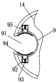
[0024] The fixing assembly 9 is provided with three groups, and the three groups of fixing assemblies 9 are equidistantly arranged in a circle with respect to the receiving rod 11. The fixing assembly 9 includes a clamping groove 91, a built-in cavity 92, a return spring 93, a clip 94 and a connecting rod 95, circular The surface of the frame plate 14 is all provided with a clamping groove 91, and the inside of the circular frame plate 14 on both sides of the inner wall of the clamping groove 91 is provided with a built-in cavity 92, and the inside of the built-in cavity 92 is welded with a connecting rod 95 by a return spring 93. And the end of the connecting rod 95 away from the return spring 93 runs through the built-in cavity 92, and the connecting rod 95 extends to the inner wall surface of the clamping groove 91 and is fixedly connected with the clip piece 94. The middle position of 14 surfaces is welded with receiving rod 11, and its receiving rod 11 is set as protruding...
PUM
 Abstract
Description
Claims
Application Information
 - R&D
- Intellectual Property
- Life Sciences
- Materials
- Tech Scout
- Unparalleled Data Quality
- Higher Quality Content
- 60% Fewer Hallucinations
Browse by: Latest US Patents, China's latest patents, Technical Efficacy Thesaurus, Application Domain, Technology Topic, Popular Technical Reports.
© 2025 PatSnap. All rights reserved.Legal|Privacy policy|Modern Slavery Act Transparency Statement|Sitemap|About US| Contact US: help@patsnap.com