Method and device for measuring dynamic impact load of wheel-side motor bearing

A wheel-side motor and impact load technology, which is used in measuring devices, testing of mechanical components, and testing of machine/structural components, etc., can solve the problem of inability to effectively simulate road vibration of motors, and achieve real and reliable vibration input, operability The effect of strong and reliable vibration excitation source

Pending Publication Date: 2020-04-28
苏州长菱测试技术有限公司
View PDF0 Cites 1 Cited by
  • Summary
  • Abstract
  • Description
  • Claims
  • Application Information

AI Technical Summary

Problems solved by technology

[0004] For this reason, the technical problem to be solved by the present invention is to overcome the problem in the prior art that the real road vibration of the motor in actual use cannot be effectively simulated, thereby providing a motor that can effectively simulate the real road vibration of the motor in actual use. Method and device for measuring dynamic impact load of wheel motor bearing

Method used


Image

  • Method and device for measuring dynamic impact load of wheel-side motor bearing
  • Method and device for measuring dynamic impact load of wheel-side motor bearing
  • Method and device for measuring dynamic impact load of wheel-side motor bearing

Examples


Embodiment 1

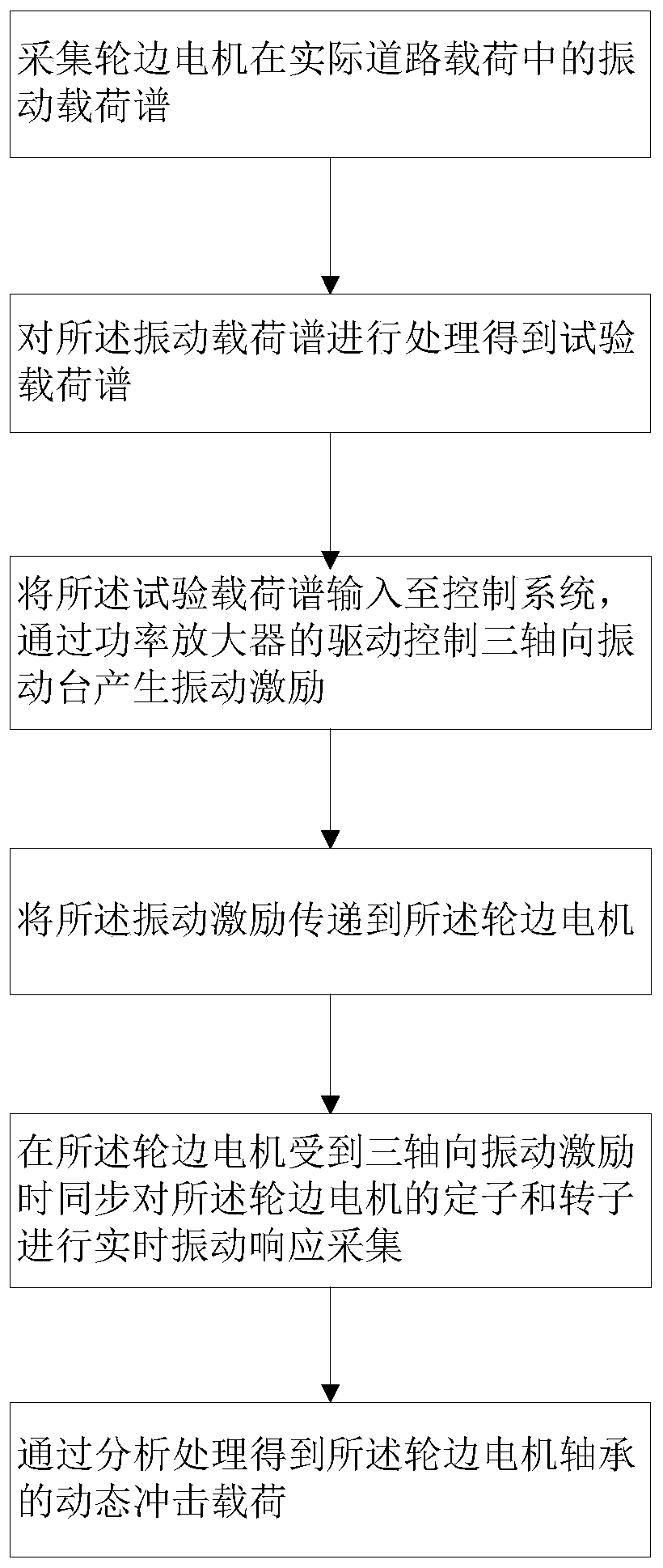
[0023] Such as figure 1 As shown, the present embodiment provides a method for measuring the dynamic impact load of the wheel motor bearing, which includes the following steps: Step S1: collecting the vibration load spectrum of the wheel motor under the actual road load, and performing the vibration load spectrum on the vibration load spectrum Process to obtain the test load spectrum; Step S2: input the test load spectrum to the control system, fix the wheel motor on the three-axis vibration table, use the test load spectrum to drive the three-axis through the power amplifier The vibration table simultaneously produces a triaxial vibration load consistent with the actual road vibration environment; Step S3: collect the vibration responses of the stator and rotor of the wheel motor in real time, and analyze and process to obtain the dynamic impact load of the motor bearing.

[0024] The method for measuring the dynamic impact load of the wheel motor bearing in this embodiment, ...

Embodiment 2

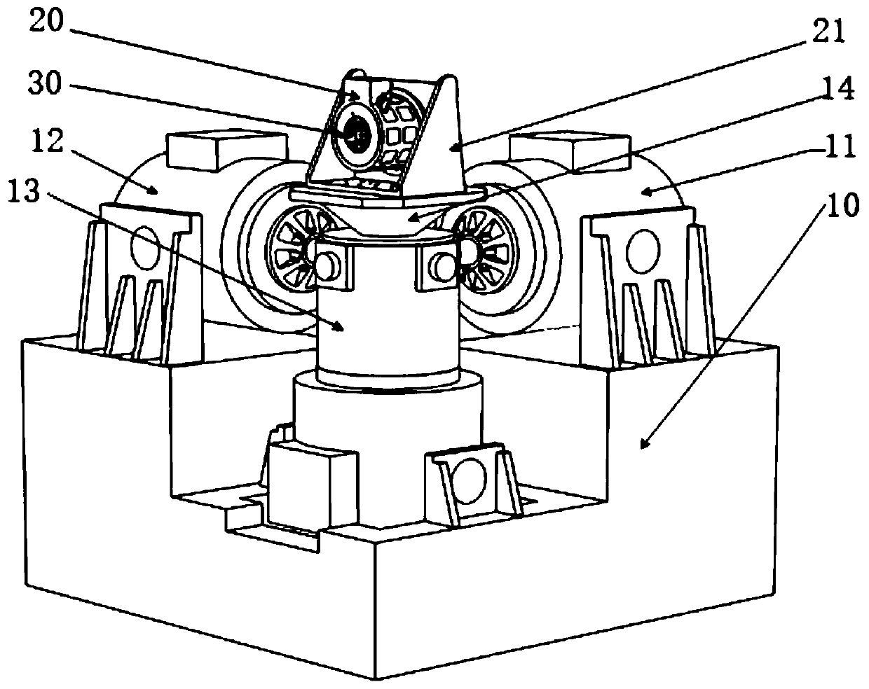
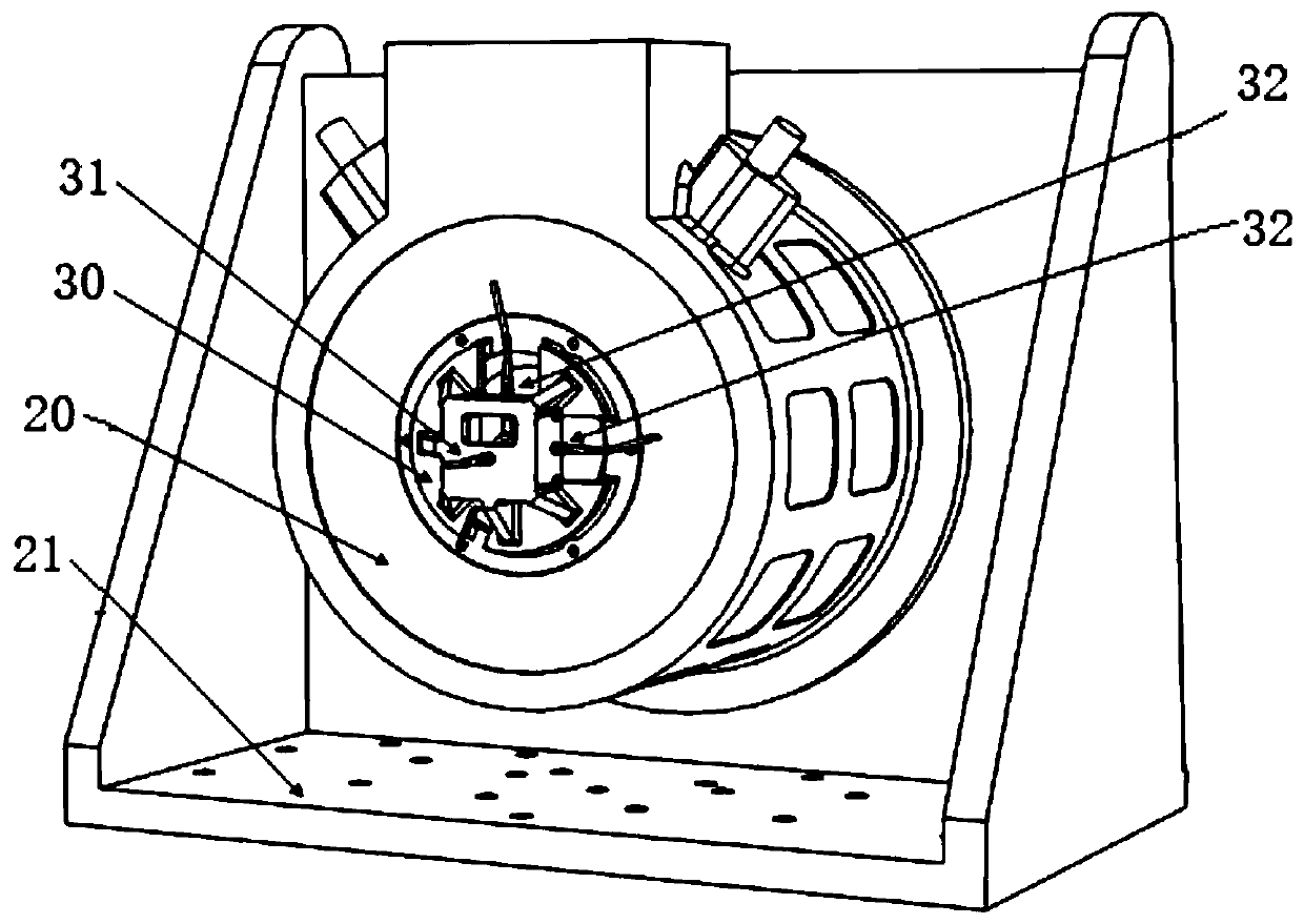
[0030] Such as figure 2 with image 3As shown, the present embodiment provides a measuring device for the dynamic impact load of the wheel motor bearing, including a first acquisition and processing system for collecting the vibration load spectrum of the wheel motor in the actual road load, and for the vibration load The spectrum is processed to obtain the test load spectrum; the control system, the control system is connected to the first acquisition and processing system, and the test load spectrum is input to the control system, the control system is connected to the power amplifier, and the power The amplifier is connected to the three-axis vibration table, and the test load spectrum is used to drive the three-axis vibration table 10 through the power amplifier to generate three axial excitation forces at the same time, and the wheel motor 20 is placed on the On the three-axis vibrating table 10; the second collection and processing system, the second collection and pro...


PUM


Abstract

The invention relates to a method and a device for measuring a dynamic impact load of a wheel-side motor bearing. The method comprises the steps: collecting a vibration load spectrum of a wheel-side motor in an actual road load, and processing the vibration load spectrum to obtain a test load spectrum; inputting the test load spectrum into a control system, fixing the wheel-side motor on a triaxial vibration table, and using the test load spectrum to drive the triaxial vibration table through a power amplifier to simultaneously generate a triaxial vibration load consistent with an actual roaduse vibration environment; and acquiring vibration responses of a stator and a rotor of the wheel-side motor in real time, and analyzing, processing and obtaining the dynamic impact load of the motorbearing. The method is high in collection precision and high in operability, a multi-axis vibration stress environment in the real use environment is ensured to be effectively simulated, and a high-precision measurement requirement of a complex environment can be well met.

Description

technical field [0001] The invention relates to the technical field of bearing measurement of wheel-side motors, in particular to a method and device for measuring dynamic impact loads of wheel-side motor bearings. Background technique [0002] The bearing of the wheel motor bears various dynamic impact loads in the actual use process, which is an important factor affecting the fatigue life of the motor bearing. Due to the existence of bearing clearance, under the actual road load vibration environment, there will be a short-lasting dynamic impact load on the inner and outer rings of the motor bearing. In actual situations, due to space constraints, sensors cannot be arranged, so effective measurement cannot be performed. [0003] Currently, in order to test the dynamic impact load, a single-axis vibration table is used for excitation. This method cannot truly and effectively simulate the multi-axial vibration environment in the actual road load. At the same time, the excita...

Claims


Application Information

Patent Timeline
Patent Type & Authority Applications(China)
IPC IPC(8): G01M13/045
CPCG01M13/045
Inventor 姚志红周伟刘绪永浦明龙
Owner 苏州长菱测试技术有限公司
Why Eureka
Try Eureka