
Hydraulic bionic ankle joint

An ankle joint and hydraulic technology, applied in the field of bionic machinery, can solve the problems of affecting the volume of the ankle joint, weight noise, high price, and laborious movement, etc., and achieve the effect of smooth foot movement curve, saving physical strength, and increasing the buffering effect of stump movement.

Pending Publication Date: 2020-05-01
北京工道风行智能技术有限公司
View PDF0 Cites 8 Cited by
  • Summary
  • Abstract
  • Description
  • Claims
  • Application Information

AI Technical Summary

Problems solved by technology

Most of the existing ankle prostheses are passive, using the deformation of the foot plate itself to meet the resilience required by the residual limb, and the movement is relatively rigid, stiff, and poor in flexibility
For crawling up and down stairs, walking up and down slopes basically requires the body swing of the assembler's stump and crotch to provide power, which makes it difficult to move, causing a lot of inconvenience to the disabled in their normal life
[0003] At present, although the research direction of calf prosthesis tends to be intelligent, the transmission device of the intelligent ankle affects the volume, weight and noise of the ankle joint. Do not abandon the assembly of intelligent prosthetics, continue to use passive ankles
In addition, domestic research mainly focuses on the realization of the function of the knee prosthesis, while the ankle joint is only used as an elastic energy storage structure to assist the human body to walk, and some key technologies have yet to be developed and perfected

Method used


Image

  • Hydraulic bionic ankle joint
  • Hydraulic bionic ankle joint
  • Hydraulic bionic ankle joint

Examples


Embodiment Construction

[0018] The present invention will be described in detail below in conjunction with the accompanying drawings and embodiments. However, it should be understood that the accompanying drawings are provided only for better understanding of the present invention, and they should not be construed as limiting the present invention.

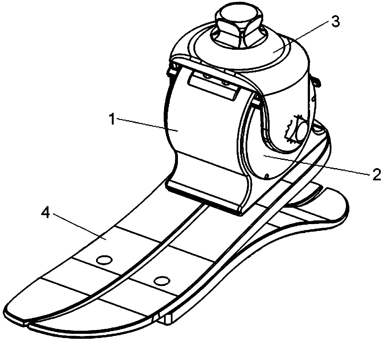
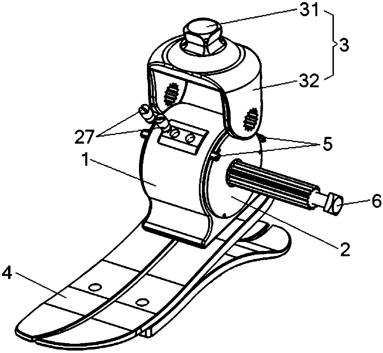
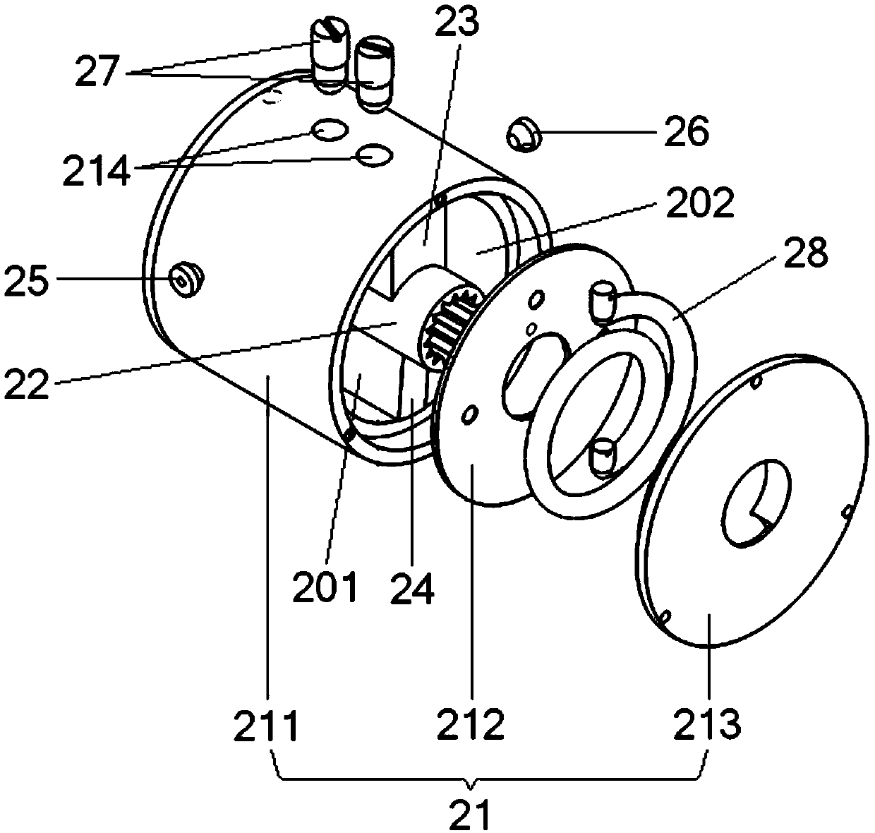
[0019] Such as figure 1 , figure 2 As shown, the hydraulic bionic ankle joint provided by the present invention includes a fixed base 1 , a hydraulic buffer mechanism 2 and a four-prism structure 3 . Among them, the lower end of the fixed seat 1 can be connected with the carbon fiber energy storage foot 4, and the hydraulic buffer mechanism 2 is press-fitted on the fixed seat 1, and the rotating shaft of the hydraulic buffer mechanism 2 is parallel to the coronal axis. The hydraulic buffer mechanism 2 is mainly used to provide bionic ankle Damping force during joint plantarflexion and dorsiflexion. The upper end of the quadrangular platform structure...


PUM


Abstract

The invention relates to a hydraulic bionic ankle joint. The bionic ankle joint is characterized by comprising: a fixed seat of which the lower end can be connected to a carbon fiber energy storage foot; a hydraulic buffer mechanism which is arranged on the fixed seat in a press fitting mode, wherein a rotating shaft of the hydraulic buffer mechanism is parallel to a coronary shaft, and the buffermechanism is used for providing damping force during plantar flexion movement and dorsal flexion movement of the bionic ankle joint; and a square pyramid frustum structural part of which the upper end can be connected to the artificial limb receiving cavity and the lower end is connected to a rotating shaft of the hydraulic buffer mechanism, and the square pyramid frustum structural part can rotate and swing forwards and backwards around the rotating shaft of the hydraulic buffer mechanism. The invention provides the hydraulic bionic ankle joint which integrates hydraulic damping and self-resetting functions, has the characteristics of light weight, small size and no noise, makes the ankle joint close to a real ankle, and provides convenient and excellent artificial limbs for more disabled people.

Description

technical field [0001] The invention relates to the technical field of bionic machinery, in particular to a hydraulic bionic ankle joint integrating hydraulic damping and self-resetting functions. Background technique [0002] In recent years, due to traffic accidents, diseases and other reasons, the number of people with amputations below the knee has gradually increased, and wearing ankle prostheses can achieve a large compensation for the missing functions of the human body. Most of the existing ankle prostheses are passive, using the deformation of the foot plate itself to meet the resilience required by the residual limb, and the movement is relatively rigid, stiff, and poor in flexibility. For crawling up and down stairs, walking up and down slopes basically requires the body swing of the assembler's stump and crotch to provide power, which makes it difficult to move and causes a lot of inconvenience to the disabled in normal life. [0003] At present, although the re...

Claims


Application Information

Patent Timeline
IPC IPC(8): A61F2/66
CPCA61F2/6607A61F2/74
Inventor 王卫刚朱金营王启宁屠晓光马耀军王琛涛
Owner 北京工道风行智能技术有限公司
Learn More