
Construction waste crushing treatment device based on crank rocker principle

A crank rocker and construction waste technology, which is applied in grain processing, magnetic separation, solid separation, etc., can solve the problems of incomplete crushing, insufficient use of crushing devices, and reduced service life of equipment, so as to ensure the crushing effect, The effect of suppressing dust scattering and increasing the service life

Active Publication Date: 2020-05-01
江西太平洋宇洪建设有限公司
View PDF5 Cites 22 Cited by
  • Summary
  • Abstract
  • Description
  • Claims
  • Application Information

AI Technical Summary

Problems solved by technology

[0003] In the recycling process of construction waste, it is necessary to crush the construction waste. However, the existing construction waste crushing devices often only use crushing rollers for one crushing process, and it is difficult to completely crush the construction waste. When crushing the block, it is likely to cause damage to the crushing roller and reduce the service life of the equipment; the crushed construction waste contains a large amount of dust, which will pollute the air; the feeding speed cannot be effectively controlled during crushing, and the If the material speed is too slow, the crushing device will not be fully used and work efficiency will be reduced. If the feeding speed is too fast, the crushing will be incomplete and the crushing effect will be poor; after crushing, the metal doped in the fine building fragments cannot be processed Separation not only affects the quality of fine building debris recycling processing, but also causes waste of metal materials

Method used


Image

  • Construction waste crushing treatment device based on crank rocker principle
  • Construction waste crushing treatment device based on crank rocker principle
  • Construction waste crushing treatment device based on crank rocker principle

Examples


Embodiment Construction

[0030] The following will clearly and completely describe the technical solutions in the embodiments of the present invention with reference to the accompanying drawings in the embodiments of the present invention. Obviously, the described embodiments are only some, not all, embodiments of the present invention. Based on the embodiments of the present invention, all other embodiments obtained by persons of ordinary skill in the art without making creative efforts belong to the protection scope of the present invention.

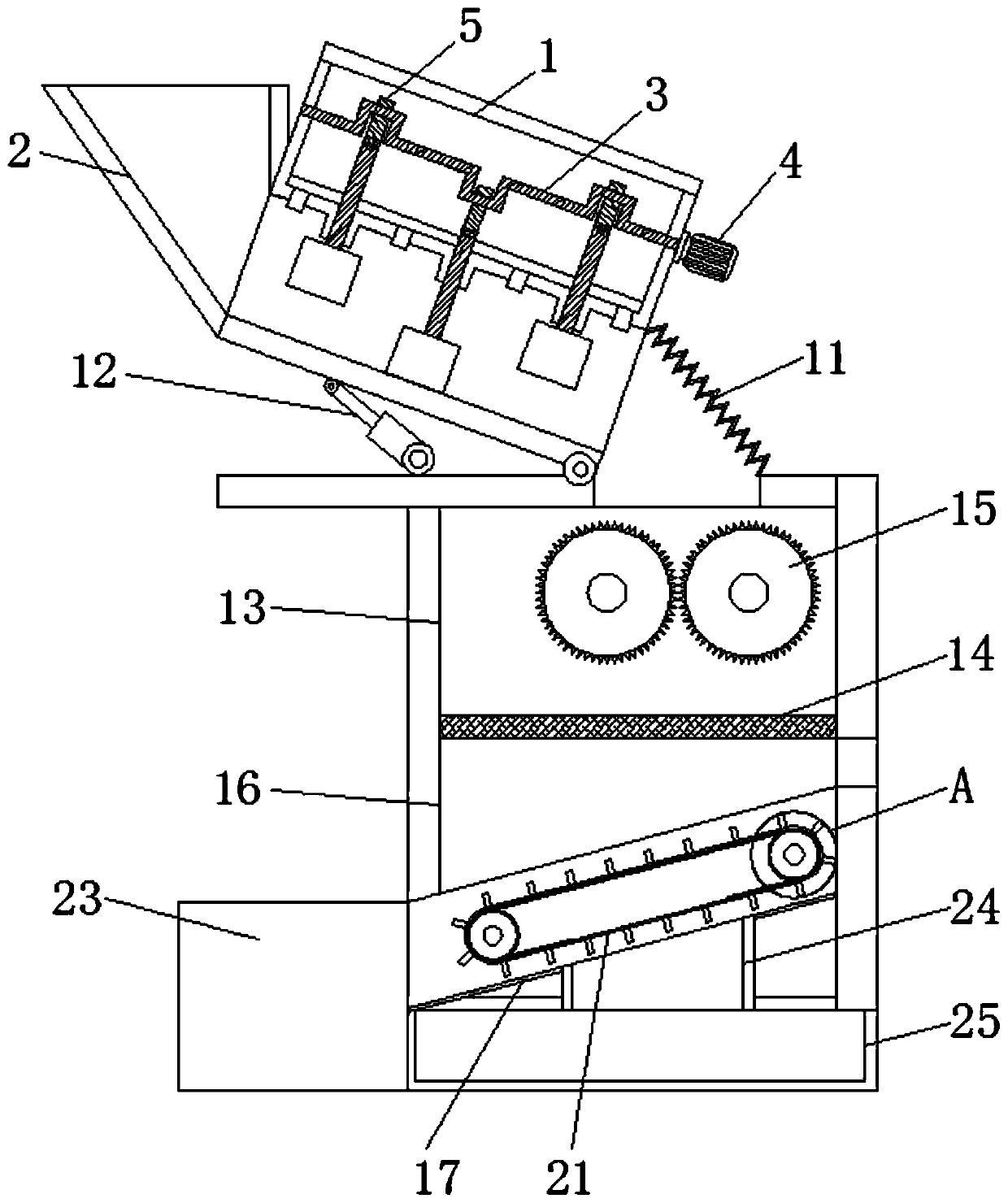
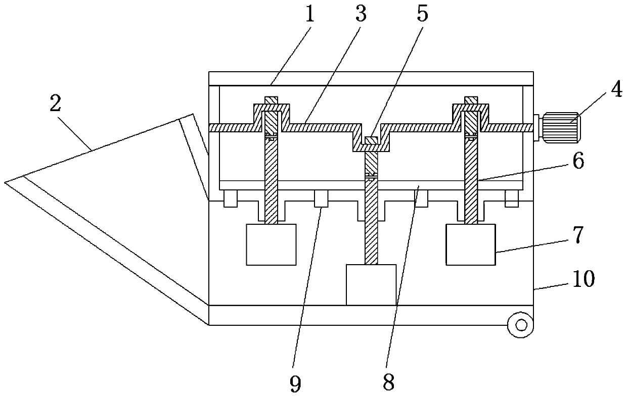
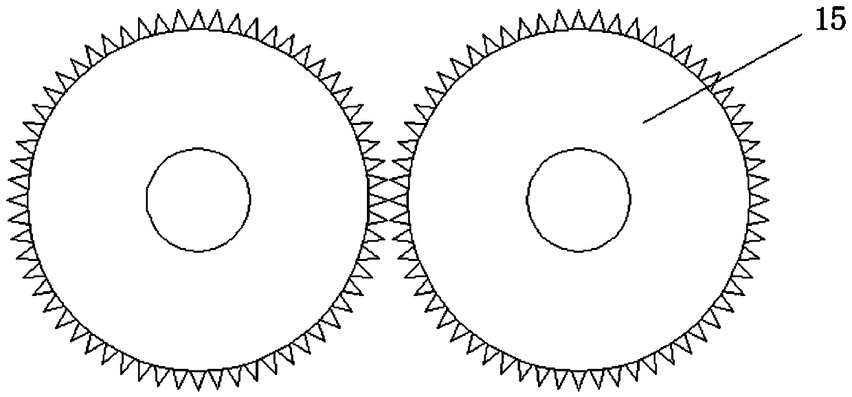
[0031] see Figure 1-4 , a construction waste crushing device based on the crank rocker principle, including a pre-crushing chamber 1, a feed port 2, a crank rocker 3, a pre-crushing motor 4, a connecting rod 5, an impact rod 6, an impact hammer 7, and a partition 8 , spray device 9, discharge port 10, corrugated cover 11, hydraulic rod 12, fine crushing chamber 13, screen 14, crushing roller 15, separation chamber 16, material guide groove 17, transmission wh...


PUM


Abstract

The invention relates to the technical field of construction waste, and discloses a construction waste crushing treatment device based on a crank rocker principle. The construction waste crushing treatment device comprises a pre-crushing chamber, wherein a feeding opening is fixedly connected to the exterior of the pre-crushing chamber, a crank rocker is movably connected to the interior of the pre-crushing chamber, a pre-crushing motor is fixedly connected to the exterior of the crank rocker, a connecting rod is movably connected to the exterior of the crank rocker, an impact rod is hinged and connected to the exterior of the connecting rod, and an impact hammer is fixedly connected to the bottom of the impact rod. The pre-crushing motor and the impact hammer are used cooperatively, and the construction waste is impacted and crushed by the impact hammer, so that the pre-crushing effect of the construction waste is achieved; and meanwhile, the impact hammer impacts the bulk construction waste and enables the bulk construction waste to be subjected to fragmentation treatment, so that the subsequent use effect of crushing rollers is guaranteed, and the bulk construction waste is prevented from damaging the crushing rollers, and the service life of the crushing device is prolonged.

Description

technical field [0001] The invention relates to the technical field of construction waste, in particular to a construction waste crushing and processing device based on the crank rocker principle. Background technique [0002] Construction waste refers to the dregs, spoils, waste materials, silt and other wastes generated during the construction, laying or demolition, and repair of various buildings, structures, and pipe networks by construction units or individuals. As people pay more attention to the environment and the recycling of resources, they also pay more and more attention to the recycling of construction waste. Construction waste can use waste construction concrete and waste bricks to produce coarse and fine aggregates, which can be used to produce concrete with corresponding strength levels. , Mortar or preparation of building materials such as blocks, wall panels, floor tiles and other products. [0003] In the recycling process of construction waste, it is nec...

Claims


Application Information

Patent Timeline
IPC IPC(8): B02C1/14B02C4/08B02C23/14B02C23/16B02C23/18B01D47/06B03C1/30
CPCB01D47/06B02C1/14B02C4/08B02C23/14B02C23/16B02C23/18B02C2023/165B02C2201/06B03C1/30
Inventor 王福亮
Owner 江西太平洋宇洪建设有限公司
Learn More