
Drainage ditch cleaning equipment for livestock breeding

A technology for cleaning equipment and drainage ditch, applied in the direction of cleaning methods using tools, cleaning methods and utensils, chemical instruments and methods, etc., can solve problems such as spending a lot of time and energy, limited cleaning range of breeders, and affecting work efficiency, etc. Achieve uniform moving speed, avoid loosening, and improve work efficiency

Inactive Publication Date: 2020-05-01
曾凡信
View PDF6 Cites 4 Cited by
  • Summary
  • Abstract
  • Description
  • Claims
  • Application Information

AI Technical Summary

Problems solved by technology

[0005] In order to overcome the limited cleaning range of the breeders, they can only use cleaning tools to brush one by one, which takes a lot of time and energy and seriously affects the shortcomings of work efficiency. Technical problem: provide a kind of animal husbandry that can improve work efficiency. Drain Cleaning Equipment

Method used


Image

  • Drainage ditch cleaning equipment for livestock breeding
  • Drainage ditch cleaning equipment for livestock breeding
  • Drainage ditch cleaning equipment for livestock breeding

Examples


Embodiment 1

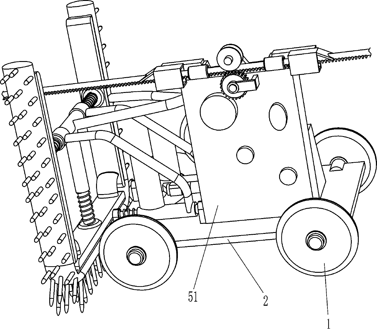
[0025] A kind of excrement ditch cleaning equipment for animal husbandry, see Figure 1-3 , including a roller 1, a mounting plate 2, a vibration mechanism 3 and a cleaning mechanism 4, two rollers 1 are installed on the front and rear sides of the mounting plate 2 through bolts, the rollers 1 on the front and rear sides are symmetrical, and the vibration mechanism is installed on the mounting plate 2 3. A cleaning mechanism 4 is installed on the vibrating mechanism 3 .

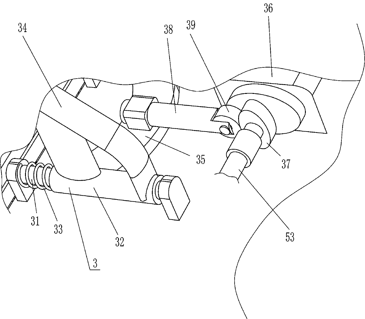
[0026] Vibration mechanism 3 includes guide rod 31, guide sleeve 32, first spring 33, mounting frame 34, connecting plate 35, drive motor 36, cam 37, drive shaft 38 and contact wheel 39, two front and rear sides on the left side of mounting plate 2 tops. Both sides are equipped with guide rods 31 by bolts, and the guide rods 31 on the front and rear sides are all slidably provided with guide sleeves 32. The guide rods 31 are wound with a first spring 33, and the right end of the first spring 33 is connected w...

Embodiment 2

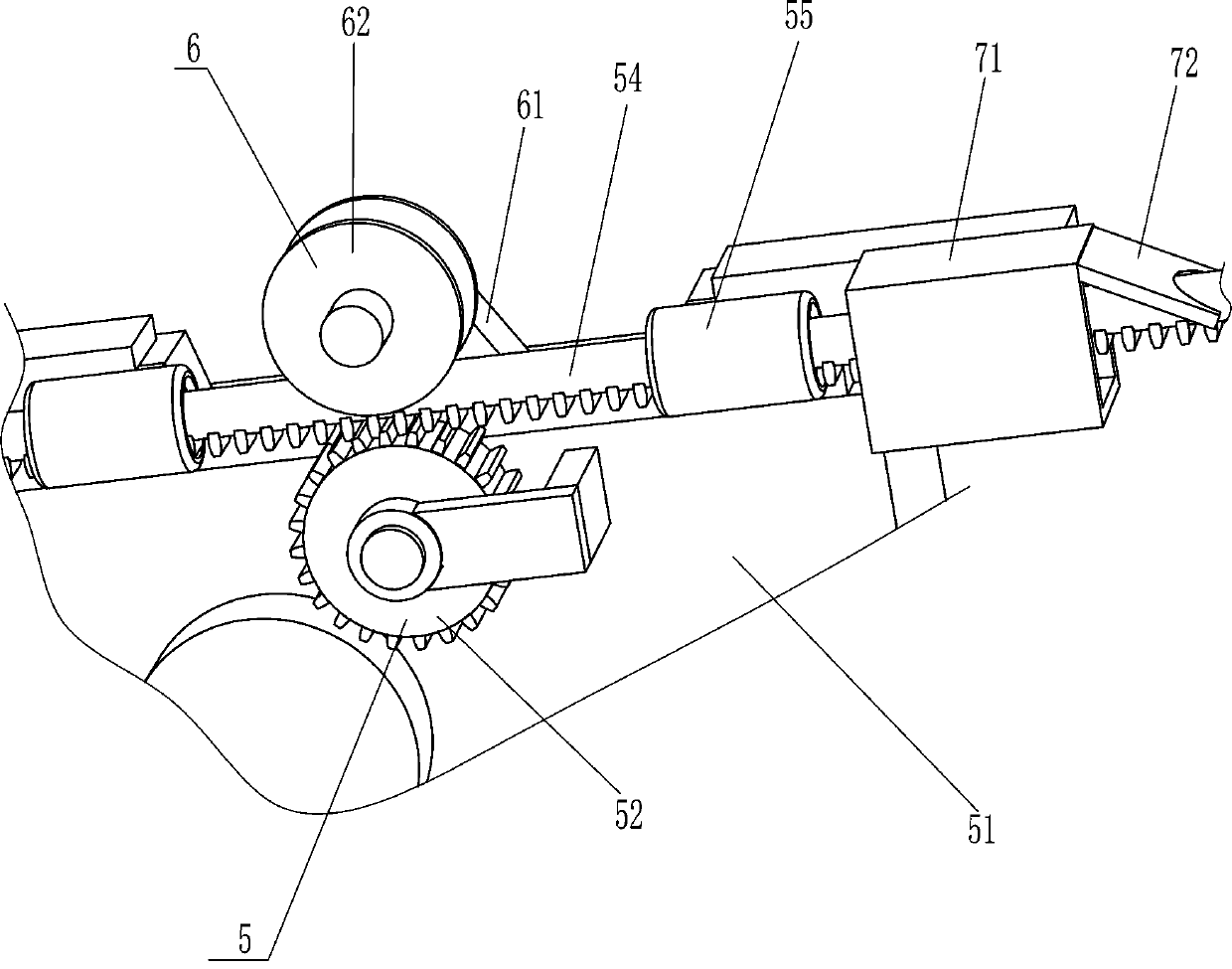
[0032] On the basis of embodiment 1, refer to figure 1 , image 3 , Figure 4 with Figure 5 , also includes moving mechanism 5, and moving mechanism 5 includes gearbox 51, gear 52, shaft coupling 53, toothed belt 54 and fixed sleeve 55, and the front side of mounting plate 2 top is equipped with gearbox 51 by bolt, and drive motor 36 The output shaft of the gearbox 51 is connected to the input end of the gearbox 51 through a coupling 53, and a gear 52 is installed on the output end of the gearbox 51. The left and right sides of the top of the gearbox 51 are connected with fixed sleeves 55, and the two fixed sleeves 55 are equipped with There is a toothed belt 54, and the toothed belt 54 can be made of rubber, and the toothed belt 54 is meshed with the gear 52.

[0033] Also includes engagement mechanism 6, and engagement mechanism 6 comprises mounting seat 61 and sheave 62, is connected with mounting seat 61 in the middle of gearbox 51 top, and mounting seat 61 is triangul...


PUM


Abstract

The invention relates to cleaning equipment, in particular to drainage ditch cleaning equipment for livestock breeding. The technical purpose is to provide the drainage ditch cleaning equipment for livestock breeding which can improve the work efficiency. The drainage ditch cleaning equipment for livestock breeding comprises idler wheels, a mounting plate and the like. The two or more idler wheelsare installed on the two sides of the mounting plate. According to the drainage ditch cleaning equipment for livestock breeding, a vibration mechanism can make a cleaning mechanism vibrate to clean the inner wall of a drainage ditch, and since the cleaning mechanism is in contact with the inner wall of the drainage ditch, the three faces of the drainage ditch can be cleaned at a time, and accordingly the work efficiency can be improved. The equipment can move leftwards through a movement mechanism, in this way, machinery is used for replacing manual operation, the movement speed of the equipment is more uniform, and each area of the inner wall of the drainage ditch can be thoroughly cleaned.

Description

technical field [0001] The invention relates to a cleaning device, in particular to a drainage ditch cleaning device for animal husbandry. Background technique [0002] Animal husbandry is a centralized, large-scale, and profit-oriented production activity. Through artificial breeding and breeding of livestock, meat, eggs, milk and other products are obtained. Animal husbandry is one of the components of agriculture. It is related to planting The industry is listed as the two pillars of agricultural production. In large-scale livestock farms, there are special excretion ditches for livestock to defecate. In order to keep the excretion ditch smooth, it is necessary to regularly clean up the excrement in the excretion ditch and clean its inner wall. Clean to avoid foul smell. [0003] At present, the breeders mainly enter the drainage ditch, and then use cleaning tools to clean the inner wall of the drainage ditch. There are three sides in the drainage ditch. In addition, in ...

Claims


Application Information

Patent Timeline
IPC IPC(8): B08B1/00B08B7/02B08B13/00
CPCB08B7/02B08B13/00B08B1/165B08B1/12
Inventor 曾凡信
Owner 曾凡信
Learn More