Polishing device used for sheet metal machining

A sheet metal and grinding plate technology, which is applied in the direction of grinding drive devices, metal processing equipment, grinding/polishing safety devices, etc., can solve problems such as poor adjustability, low grinding flexibility, and strict requirements for fixing parts, and achieve improved Improve the quality of machining, improve the quality of grinding, and improve the flexibility of grinding

Inactive Publication Date: 2020-05-01
卢海珍
View PDF5 Cites 0 Cited by
  • Summary
  • Abstract
  • Description
  • Claims
  • Application Information

AI Technical Summary

Problems solved by technology

[0003] After sheet metal processing, it is necessary to polish the burrs on the surface of the parts. The existing grinding devices for sheet metal processed parts have low flexibility in grinding, poor adjustability of grinding, and strict requirements for fixing parts.

Method used


Image

  • Polishing device used for sheet metal machining
  • Polishing device used for sheet metal machining
  • Polishing device used for sheet metal machining

Examples


Embodiment 1

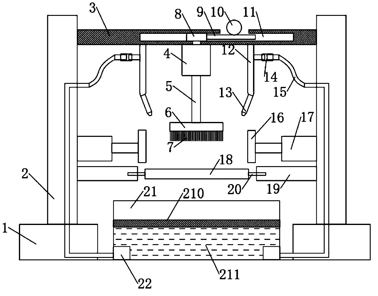
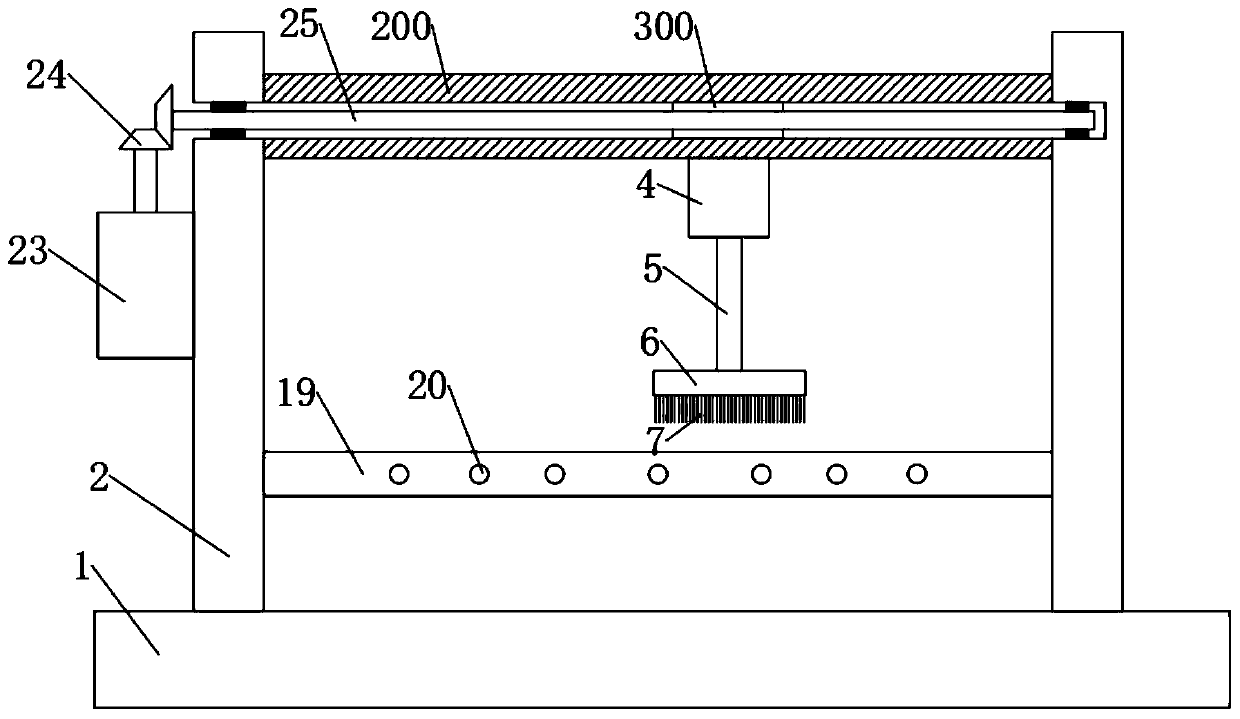
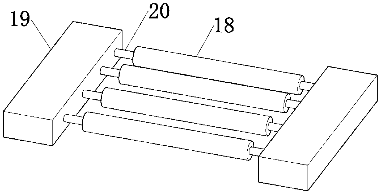
[0025] Such as Figure 1-4 As shown, a grinding device for sheet metal processing includes a mounting base 1, on which a column 2 is symmetrically fixed, and a cross bar 3 is arranged between the column 2, and a cross bar 3 is movably installed with The first motor 4, the output shaft 5 of the first motor 4 is provided with a grinding plate 6, the lower side of the grinding plate 6 is evenly provided with a grinding brush 7, and the lower side of the grinding plate 6 is provided with a mounting plate 19 , the mounting plate 19 is rotatably connected with a roller 18, the motor is provided with a slider 8, the cross bar 3 is provided with a chute 11, the slider 8 cooperates with the chute 11, and the chute 11 A worm 9 is fixedly connected to the block 8, and the worm 9 is installed in a chute 11, and the worm 9 is connected with a turbine 10, and the turbine 10 is connected with a power unit.

[0026] Specifically, the first motor 4 is installed on the crossbar 3, and the grin...

Embodiment 2

[0037] This embodiment is a further improvement and limitation of embodiment 1 on the basis of embodiment 1.

[0038] A kind of grinding device for sheet metal processing, including all parts in embodiment 1, also includes:

[0039] Further, the lower side of the drum 18 is provided with a water tank 21 filled with polishing fluid 211, the water tank 21 is provided with a filter screen 210, and the bottom of the water tank 21 is equipped with a water pump 22, and the water pump 22 is connected to the water pipe 12 , the crossbar 3 is equipped with a nozzle 13, the nozzle 13 is aligned with the grinding plate 6, the nozzle 13 is fixedly connected to the crossbar 3 through a water pipe 12, and a hose 15 is connected between the water pipe 12 and the column 2, The water pipe 12 is connected to a hose 15 through a connector 14 .

[0040] Specifically, in the process of parts grinding, due to the difference of parts materials, the same grinding brush 7 may have completely differen...


PUM


Abstract

The invention discloses a polishing device used for sheet metal machining, and relates to the technical field of machining. The polishing device mainly solves the problems that an existing part polishing device is poor in flexibility and high in part installation requirement. The device comprises an installation base. Stand columns are symmetrically fixed to the installation base. A transverse rodis arranged between the stand columns. A first motor is movably installed on the transverse rod. A polishing plate is arranged on an output shaft of the first motor. Installation plates are arrangedbelow the polishing plate. A roller is installed on the installation plates. A water tank is arranged below the roller. A filter screen is arranged in the water tank. A water pump is installed at thebottom of the water tank and is connected with a water pipe. Spray nozzles are installed on the portions, on the two sides of the polishing plate, of the transverse rod. A slide block is arranged on the motor. A slide groove is formed in the transverse rod. The slide block and the slide groove are matched with each other. The polishing device can be flexibly adjusted through the polishing plate, the slide block, the slide groove and the like, and the polishing effect is greatly enhanced.

Description

technical field [0001] The invention relates to the technical field of mechanical processing, in particular to a grinding device for sheet metal processing. Background technique [0002] Sheet metal processing is a key technology that sheet metal technicians need to master, and it is also an important process for forming sheet metal products. Sheet metal processing includes traditional cutting, punching, bending and forming methods and process parameters, as well as various cold stamping die structures and process parameters, various equipment working principles and operating methods, and new stamping technology. and new technology. Part metal sheet processing is called sheet metal processing. [0003] After sheet metal processing, the burrs on the surface of the parts need to be polished. The existing grinding devices for sheet metal processed parts have low grinding flexibility, poor adjustability of grinding, and strict requirements for fixing parts. Contents of the i...

Claims


Application Information

Patent Timeline
Patent Type & Authority Applications(China)
IPC IPC(8): B24B19/00B24B41/06B24B47/20B24B47/22B24B55/02
CPCB24B19/00B24B41/06B24B47/20B24B47/22B24B55/02
Inventor 卢海珍
Owner 卢海珍
Why Eureka
Try Eureka