

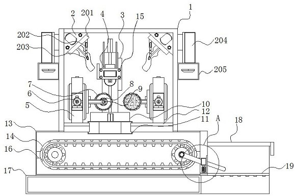
Integrated cutting and grinding equipment with transmission structure and for mold slide inserts
A technology of transmission structure and row position, which is applied in the direction of grinding/polishing equipment, metal processing equipment, other manufacturing equipment/tools, etc. It can solve the problems of inability to grind and cut items, inconvenient use for users, and inability to turn them over. Achieve the effects of improving grinding efficiency, facilitating grinding operations, and good hidden effects
- Summary
- Abstract
- Description
- Claims
- Application Information
AI Technical Summary
Problems solved by technology
Method used
Image

Examples
Embodiment Construction
[0026] The technical solutions in the embodiments of the present invention will be clearly and completely described below in conjunction with the accompanying drawings in the embodiments of the present invention. Obviously, the described embodiments are only some of the embodiments of the present invention, not all of them. Based on The embodiments of the present invention and all other embodiments obtained by persons of ordinary skill in the art without making creative efforts belong to the protection scope of the present invention.
[0027] In the description of the present invention, unless otherwise stated, the meaning of "plurality" is two or more; the terms "upper", "lower", "left", "right", "inner", "outer" , "front end", "rear end", "head", "tail", etc. indicate the orientation or positional relationship based on the orientation or positional relationship shown in the drawings, and are only for the convenience of describing the present invention and simplifying the desc...
PUM
 Abstract
Description
Claims
Application Information